CAN Connectivity in an Automotive Application
This example uses Vehicle Network Toolbox to implement a distributed Electronic Control Unit (ECU) network on CAN for an automobile using Simulink®. The CAN messages used are defined in the CAN database file,canConnectivityForVehicle.dbc.
Vehicle Network Toolbox™ provides Simulink blocks for transmitting and receiving live messages via Simulink models over Controller Area Networks (CAN). This example uses the CAN Configuration, CAN Pack, CAN Transmit, CAN Receive and CAN Unpack blocks to perform data transfer over a CAN bus.
MathWorks virtual CAN channels were used for this example. You can however connect your models to other supported hardware.
Model Description
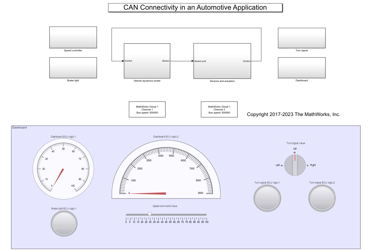
The model consists of the following subsystems: Vehicle dynamics model, Sensors and actuators, Turn signal, Dashboard, brake light and Speed controller. The Vehicle dynamics model represents the automobile (the environment), and the other subsystems represent the various nodes on the CAN bus.
Vehicle Dynamics Model
This subsystem defines the equations of motion of the automobile. The inputs are the throttle and brake actuator positions. The outputs are the engine RPM and vehicle speed, that are multiplexed into a single signal.
Sensors and Actuators

This subsystem consists of the throttle and brake actuators, and the RPM and vehicle speed sensors. The actuators receive the throttle and the brake commands via the CAN bus. The actuator outputs (control) are fed to the vehicle dynamics model.
制动执行器还发出信号,告知制动器是否被驱动。该信号以100 Hz采样,并将其传输到CAN总线中。来自车辆动力学模型的发动机RPM和车辆速度信号输入了该子系统,并以100 Hz采样并将其传输到CAN总线中。
Dashboard
The dashboard is the interface between the vehicle and the driver. The commanded speed can be set by the user using the slider (Speed command:Value). The turn signal can be operated using the rotary switch (Turn signal:Value).
The speed command and turn signal status signals are transmitted into the CAN bus. The sampled vehicle speed and engine RPM are read from the CAN bus and displayed on the speedometer and the tachometer respectively.
Speed Controller
速度控制器将命令发送到执行器,以将车辆速度推向指挥值。车辆速度和指挥速度是从CAN总线读取的。油门和制动命令由相应的离散比例 - 积分控制器计算。执行器命令将传输到CAN总线中。
Brake Light
The Brake light subsystem receives the brake actuator status signal from the CAN bus and appropriately operates the brake lights. Whenever the brakes are actuated, the brake lights are turned on.
Turn Signal
The turn signal subsystem receives the turn signal status message from the CAN bus and appropriately activates the turn signals. The left turn signal light blinks periodically when the rotary switch is set to the "Left" position, and the right turn signal light blinks periodically when the rotary switch is set to the "Right" position.
You can also select a web site from the following list:
Americas
- América Latina(Español)
- Canada(English)
- United States(English)
Europe
- Belgium(English)
- 丹麦(English)
- Deutschland(Deutsch)
- España(Español)
- Finland(English)
- France(Français)
- Ireland(English)
- Italia(Italiano)
- Luxembourg(English)
- Netherlands(English)
- 挪威(English)
- Österreich(Deutsch)
- Portugal(English)
- Sweden(English)
- Switzerland
- United Kingdom(English)