Digital Video Broadcasting-Satellite-Second Generation (DVB-S2) is a physical layer standard to support high data-rate satellite communications in the presence of RF impairments in space by providing specifications for framing structure, channel coding, modulation systems, and spectrum efficiency. DVB-S2 is a significant upgrade to the first-generation Digital Video Broadcasting-Satellite (DVB-S) standard. The DVB-S2 standard can support a wide range of applications, including:
- News-gathering from remote locations
- HDTV broadcast services
- Internet access
- Cellular backhauling
- Government and defense networks
Some DVB-S2 characteristics that enable high throughput are:
- Forward error correction based on low-density parity check (LDPC) codes concatenated with Bose, Chaudhuri, and Hocquenghem (BCH) codes
- Adaptive coding and modulation (ACM) based on channel conditions
- 28 combinations of modulation and code rates (MODCODs)
- Signal constellations optimized for linear and nonlinear channels
- Variable bandwidth spectrum shaping that maximizes spectrum efficiency
Using Modeling and Simulation to Design DVB-S2 Systems
Figure 1 shows the components that must be modeled and simulated to design a DVB-S2 system. Signals representing a DVB-S2 transmitter are created by waveform generator. RF impairments typical of satellite communications channels are represented by mathematical models such as additive white Gaussian noise (AWGN) and others. The models allow engineers to explore design tradeoffs and test ideas in their DVB-S2 receiver designs.MATLAB®provides functions and apps that implement these capabilities.
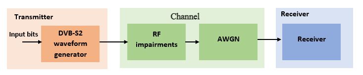
Figure 1 Modeling and simulation components for designing a DVB-S2 receiver. The transmitter is modeled with waveform generation, and the channel is modeled as RF impairments along with AWGN.
DVB-S2 Waveform Generation
DVB-S2 waveform generation is required to design, test, and refine a DVB-S2 receiver. DVB-S2 waveforms can be generated in MATLAB usingdvbs2WaveformGenerator. Major elements of DVB-S2 waveforms that adhere to the ETSI EN 302 307-1 V1.4.1 standard include the following.
- Input stream format:
- Transport stream - Fixed packet length for MPEG payload delivery
- Generic stream - Variable packet length for multi-protocol encapsulation (IPv4, IPv6, MPEG, etc.)
- Modulation type and code rate: Determined by MODCOD per Table 12 of ETSI EN 302 307-1 V1.4.1
- Roll-off factor:
- Supported roll-off factors are 0.2, 0.25, and 0.35
- Symbol rate calculated as B/(1+R), where B is the channel bandwidth, and R is the transmit filter roll-off factor
- Pilot symbols: Optionally added at the transmitter for carrier recovery at the receiver
RF Impairments in a Typical DVB-S2 Signal
DVB-S2 links suffer from several significant RF impairments, such as weather events, poor-quality oscillators, thermal noise, and Doppler due to satellite velocity. The following RF impairments associated with DVB-S2 satellite links can be measured in MATLAB.
- Phase noise:
- Describes oscillator stability in the frequency domain.
- comm.PhaseNoisecan generate phase noise at the transmitter or receiver
- Carrier frequency offset (CFO):
- With low-Earth-orbit satellites, CFO can be as high as 20% of the symbol rate, as shown in Figure 2
- comm.PhaseFrequencyOffsetcan be used to simulate CFO
- 采样时钟的fset (SCO): Caused by misalignment of transmitter and receiver sampling clocks
- Additive white gaussian noise (AWGN):awgncan be used to generate thermal noise

Figure 2 Plot of transmitted and received DVB-S2 spectra in MATLAB usingSpectrum Analyzer, where the received signal is affected by significant CFO
DVB-S2 Receiver Design
Because of the large CFO in DVB-S2 links, receiver algorithms include separate coarse and fine frequency impairment correction blocks. The coarse frequency block is applied even before matched filtering so that the matched filter filters only noise and not the desired signal. A more detailed description of receiver design can be found in the example titledEnd-to-end DVB-S2 simulation. Figure 3 shows a typical dataflow for a DVB-S2 receiver.

Figure 3 Typical dataflow for a DVB-S2 receiver
Figure 4 shows a DVB-S2 constellation diagram of received and synchronized data for 32APSK (amplitude phase shift keying) in MATLAB. Four additional points between the two outermost rings are pilot symbols, encircled with red. This constellation is captured with Es/No at 20 dB and a 3-MHz CFO, 5-ppm SCO, and 36-MHz bandwidth.

Figure 4 DVB-S2 constellation plot diagram of received and synchronized data for 32APSK in MATLAB usingscatterplot
DVB-S2X – An Extension to DVB-S2
The Digital Video Broadcasting-Satellite-Second Generation Extended (DVB-S2X) standard enhances the support provided for core DVB-S2 applications and improves overall efficiency of communication through satellite links. The DVB-S2X standard supports these additional features:
- More granularity of modulation and code rates, supporting 116 MODCODs
- Smaller filter roll-off options for better bandwidth utilization
- Higher-order modulation schemes (64APSK, 128APSK, 256APSK)
- More scrambling options for critical co-channel interference scenarios due to high data-rate requirements, many TV channels, and other neighboring services
- Very low signal-to-noise ratio (VLSNR) mode for mobile applications
Figure 5 shows a DVB-S2X constellation diagram of received and synchronized data for 64APSK in MATLAB. The constellation is captured with Es/No at 25 dB, and 2-MHz CFO, 2-ppm SCO, and 36-MHz bandwidth.

Figure 5 DVB-S2X constellation diagram of received and synchronized data for 64APSK in MATLAB usingscatterplot
Thedvbs2xWaveformGeneratorimplements a DVB-S2X waveform generation compliant with ETSI EN 302 307-2. You can find more information on DVB-S2X atend-to-end DVB-S2X simulation. DVB-S2X receiver and transmitter designs follow the same workflows as discussed earlier for DVB-S2.
Why Are DVB-S2 and DVB-S2X Important?
- DVB-S2 and DVB-S2X were established for use in modern applications like high-quality video broadcasting and satellite Internet
- DVB-S2 and DVB-S2X capitalize on recent hardware improvements and offer high spectrum efficiency
- DVB-S2 has been widely adopted since its advent in 2005 and is likely to remain relevant for many years with the additional features in DVB-S2X
DVB-S2/S2X with MATLAB
MATLAB and卫星通信工具箱™include functionalities to design and test DVB-S2 and DVB-S2X waveforms and their receivers. You can use MATLAB to:
- Generate DVB-S2 and DVB-S2X standard waveforms
- Add RF impairments to the transmitted DVB-S2 and DVB-S2X signals
- Design optimal receivers for DVB-S2 and DVB-S2X
- Design, test, and perform end-to-end link-level simulation of DVB-S2 and DVB-S2X systems
- Generate portable C/C++ source code usingMATLAB Coder™to speed processing and incorporate algorithms designed in MATLAB into legacy C/C++ code for deployment