802.11n Packet Error Rate Simulation for 2x2 TGn Channel
This example shows how to measure the packet error rate of an IEEE® 802.11n™ HT link using an end-to-end simulation with a fading TGn channel model and additive white Gaussian noise.
介绍
In this example an end-to-end simulation is used to determine the packet error rate for an 802.11n HT [1]与SNR点选择的褪色通道链接。在每个SNR点,多个数据包通过通道传输,解调并恢复了PSDU。将PSDU与传输以确定数据包误差数的数量相比,因此将数据包错误率进行了比较。数据包检测,正时同步,载波频率偏移校正和相位跟踪由接收器执行。下图总结了每个数据包的处理。

This example also demonstrates how aparforloop can be used instead of aforloop when simulating each SNR point to speed up a simulation. Theparfor作为并行计算工具箱™的一部分,功能并行执行每个SNR的处理,以减少总仿真时间。
Waveform Configuration
一个802.11n HT transmission is simulated in this example. The HT format configuration object,wlanhtconfig, contains the format specific configuration of the transmission. The properties of the object contain the configuration. In this example the object is configured for a 20 MHz channel bandwidth, 2 transmit antennas, 2 space time streams and no space time block coding.
% Create a format configuration object for a 2-by-2 HT transmissioncfgHT = wlanHTConfig; cfgHT.ChannelBandwidth ='CBW20';% 20 MHz channel bandwidthcfgHT.NumTransmitAntennas = 2;% 2 transmit antennascfght.numspacetimestreams = 2;% 2 space-time streamscfgHT.PSDULength = 1000;% PSDU length in bytescfgHT.MCS = 15;%2个空间流,64-QAM速率-5/6cfgHT.ChannelCoding ='BCC';% BCC channel coding
Channel Configuration
In this example a TGn N-LOS channel model is used with delay profile Model-B. For Model-B when the distance between transmitter and receiver is greater than or equal to five meters, the model is NLOS. This is described further inwlanTGnChannel.
% Create and configure the channeltgnChannel = wlanTGnChannel; tgnChannel.DelayProfile ='Model-B';tgnChannel.numtransmitantennas = cfght.numtransmitantennas;tgnchannel.numreceiveantennas = 2;TGNCHANNEL.TRANSMITRECEVIERSISTANCE = 10;NLOS的米%距离tgnChannel.LargeScaleFadingEffect ='None';tgnChannel.NormalizeChannelOutputs = false;
仿真参数
对于每一个信噪比阿宝int in the vectorsnra number of packets are generated, passed through a channel and demodulated to determine the packet error rate.
snr = 25:10:45;
The number of packets tested at each SNR point is controlled by two parameters:
maxNumPEsis the maximum number of packet errors simulated at each SNR point. When the number of packet errors reaches this limit, the simulation at this SNR point is complete.maxnumpacketsis the maximum number of packets simulated at each SNR point and limits the length of the simulation if the packet error limit is not reached.
The numbers chosen in this example will lead to a very short simulation. For meaningful results we recommend increasing the numbers.
maxNumPEs = 10;% The maximum number of packet errors at an SNR pointmaxnumpackets = 100;% The maximum number of packets at an SNR point
Set the remaining variables for the simulation.
% Get the baseband sampling ratefs = wlanSampleRate(cfgHT);% Get the OFDM infoofdmInfo = wlanHTOFDMInfo('HT-Data',cfgHT);% Set the sampling rate of the channeltgnChannel.SampleRate = fs;% Indices for accessing each field within the time-domain packetind = wlanFieldIndices(cfgHT);
Processing SNR Points
对于每一个信噪比阿宝int a number of packets are tested and the packet error rate calculated.
对于每个数据包,都会发生以下处理步骤:
A PSDU is created and encoded to create a single packet waveform.
The waveform is passed through a different realization of the TGn channel model.
AWGN is added to the received waveform to create the desired average SNR per active subcarrier after OFDM demodulation.
The packet is detected.
Coarse carrier frequency offset is estimated and corrected.
Fine timing synchronization is established. The L-STF, L-LTF and L-SIG samples are provided for fine timing to allow for packet detection at the start or end of the L-STF.
估计和校正良好的载波频率偏移量。
The HT-LTF is extracted from the synchronized received waveform. The HT-LTF is OFDM demodulated and channel estimation is performed.
The HT Data field is extracted from the synchronized received waveform. The PSDU is recovered using the extracted field and the channel estimate.
Aparfor循环可用于并行化SNR点的处理。为了启用并行计算以增加速度评论“ for”语句并取消下面的“ parfor”陈述。
S = numel(snr); packetErrorRate = zeros(S,1);%parfor i = 1:S % Use 'parfor' to speed up the simulationfori = 1:S% Use 'for' to debug the simulation%设置随机的随机子流索引,以确保每个索引% iteration uses a repeatable set of random numbersstream = RandStream('combRecursive','Seed',0); stream.Substream = i; RandStream.setGlobalStream(stream);% Account for noise energy in nulls so the SNR is defined per% active subcarrierpacketSNR = snr(i)-10*log10(ofdmInfo.FFTLength/ofdmInfo.NumTones);%循环模拟多个数据包numPacketErrors = 0; n = 1;% Index of packet transmittedwhilenumpacketerrors <= maxnumpes && n <= maxnumpackets% Generate a packet waveformtxPSDU = randi([0 1],cfgHT.PSDULength*8,1);% PSDULength in bytestx = wlanWaveformGenerator(txPSDU,cfgHT);% Add trailing zeros to allow for channel filter delaytx = [tx;cfgHT.NumTransmitAntennas 0(15日)];%#ok%通过TGN通道模型传递波形reset(tgnChannel);%重置通道以实现不同rx = tgnChannel(tx);% Add noiserx = awgn(rx,packetSNR);%数据包检测并确定粗数据包偏移coarsePktOffset = wlanPacketDetect(rx,cfgHT.ChannelBandwidth);ifisempty(coarsePktOffset)% If empty no L-STF detected; packet errornumPacketErrors = numPacketErrors+1; n = n+1;continue;% Go to next loop iterationend% Extract L-STF and perform coarse frequency offset correctionlstf = rx(croumpktoffset+(ind.lstf(1):ind.lstf(2)),:);croumfreqoff = wlancoarsecfoestimate(lstf,cfght.channelbandwidth);rx = venureationoffset(rx,fs,-coarsefreqoff);% Extract the non-HT fields and determine fine packet offsetnonhtfields = rx(coarsePktOffset+(ind.LSTF(1):ind.LSIG(2)),:); finePktOffset = wlanSymbolTimingEstimate(nonhtfields,...cfgHT.ChannelBandwidth);%确定最终数据包偏移pktOffset = coarsePktOffset+finePktOffset;% If packet detected outwith the range of expected delays from the% channel modeling; packet errorifpktOffset>15 numPacketErrors = numPacketErrors+1; n = n+1;continue;% Go to next loop iterationend% Extract L-LTF and perform fine frequency offset correctionlltf = rx(pktOffset+(ind.LLTF(1):ind.LLTF(2)),:); fineFreqOff = wlanFineCFOEstimate(lltf,cfgHT.ChannelBandwidth); rx = frequencyOffset(rx,fs,-fineFreqOff);% Extract HT-LTF samples from the waveform, demodulate and perform% channel estimationhtltf = rx(pktOffset+(ind.HTLTF(1):ind.HTLTF(2)),:); htltfDemod = wlanHTLTFDemodulate(htltf,cfgHT); chanEst = wlanHTLTFChannelEstimate(htltfDemod,cfgHT);% Extract HT Data samples from the waveformhtdata = rx(pktOffset+(ind.HTData(1):ind.HTData(2)),:);%估计HT数据字段中的噪声功率nvarht = htnoiseestimate(htdata,chanest,cfght);%恢复HT数据中传输的PSDUrxPSDU = wlanHTDataRecover(htdata,chanEst,nVarHT,cfgHT);% Determine if any bits are in error, i.e. a packet errorpacketError = any(biterr(txPSDU,rxPSDU)); numPacketErrors = numPacketErrors+packetError; n = n+1;end% Calculate packet error rate (PER) at SNR pointpacketRorrate(i)= numpacketerrors/(n-1);disp([['SNR 'num2str(snr(i))...' completed after 'num2str(n-1)' packets,'...' PER: 'num2str(packetErrorRate(i))]);end
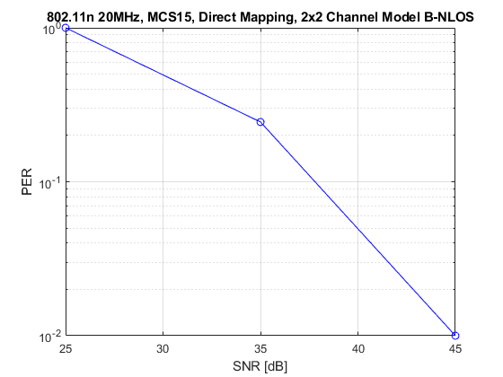
SNR 25 completed after 11 packets, PER: 1 SNR 35 completed after 45 packets, PER: 0.24444 SNR 45 completed after 100 packets, PER: 0.01
Plot Packet Error Rate vs SNR Results
figure; semilogy(snr,packetErrorRate,'-ob');grid上;xlabel('SNR [dB]');ylabel('PER');标题('802.11n 20MHz, MCS15, Direct Mapping, 2x2 Channel Model B-NLOS');
进一步探索
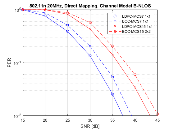
The number of packets tested at each SNR point is controlled by two parameters;maxNumPEs和maxnumpackets. For meaningful results it is recommended that these values should be larger than those presented in this example. Increasing the number of packets simulated allows the PER under different scenarios to be compared. Try changing the transmit encoding scheme to LDPC and compare the packet error rate. As an example, the figure below was created by running the example formaxNumPEs:200和maxnumpackets: 10000, with four different configurations; 1x1 and 2x2 with BCC and LDPC encoding.
Appendix
This example uses the following helper functions:
Selected Bibliography
IEEE STD 802.11™-2020。信息技术的IEEE标准 - 系统之间的电信和信息交换 - 本地和大都市区域网络 - 特定要求 - 第11部分:无线LAN媒体访问控制(MAC)和物理层(PHY)规格。
You can also select a web site from the following list:
Americas
- AméricaLatina(Español)
- Canada(English)
- United States(English)
欧洲
- Belgium(English)
- 丹麦(English)
- Deutschland(德意志)
- España(Español)
- Finland(English)
- 法国(Français)
- 爱尔兰(English)
- Italia(Italiano)
- Luxembourg(English)
- Netherlands(English)
- 挪威(English)
- Österreich(德意志)
- Portugal(English)
- Sweden(English)
- Switzerland
- United Kingdom(English)