Airplane Tracking Using ADS-B Signals in Simulink
This example shows you how to track planes by processing Automatic Dependent Surveillance-Broadcast (ADS-B) signals using Simulink® and Communications Toolbox™. You can either use captured and saved signals, or receive signals in real time using the RTL-SDR Radio or ADALM-PLUTO Radio. The example can show the tracked planes on a map, if you have the Mapping Toolbox™.
Required Hardware and Software
To run this example using captured signals, you need the following software:
万博1manbetx
Communications Toolbox
To receive signals in real time, you also need one of the following SDR devices and the corresponding support package Add-On:
RTL-SDR radio and the corresponding Communications Toolbox Support Package for RTL-SDR Radio Add-On
ADALM-PLUTO广播和相应的注意ions Toolbox Support Package for Analog Devices® ADALM-PLUTO Radio Add-On
For a full list of Communications Toolbox supported SDR platforms, refer to Supported Hardware section ofSoftware Defined Radio (SDR) discovery page.
Introduction
For an introduction on the Mode-S signaling scheme and ADS-B technology for tracking aircraft, refer to theAirplane Tracking Using ADS-B SignalsMATLAB® example.
Receiver Structure
The following block diagram summarizes the receiver code structure. The processing has four main parts: Signal Source, Physical Layer, Message Parser, and Data Viewer.
![]()
Signal Source
This example can use signal sources from a:
''Captured Signal'': Over-the-air signals written to a file and sourced using a baseband file reader block at 2.4 Msps
''RTL-SDR Radio'': RTL-SDR radio at 2.4 Msps
''ADALM-PLUTO'': ADALM-PLUTO radio at a sample rate of 12 Msps
Here the extended squitter message is 120 micro seconds long, so the signal source is configured to process enough samples to contain 180 extended squitter messages at once, and setSamplesPerFrame信号的相应属性。其余的e algorithm searches for Mode-S packets in this frame of data and outputs all correctly identified packets. This type of processing is defined as batch processing. An alternative approach is to process one extended squitter message at a time. This single packet processing approach incurs 180 times more overhead than the batch processing, while it has 180 times less delay. Since the ADS-B receiver is delay tolerant, batch processing was used.
Physical Layer
The baseband samples received from the signal source are processed by the physical (PHY) layer to produce packets that contain the PHY layer header information and the raw message bits. The following diagram shows the physical layer structure.
![]()
The RTL-SDR radio is capable of using a sampling rate in the range [200e3, 2.8e6] Hz. When RTL-SDR radio is the source, the example uses a sampling rate of 2.4e6 Hz and interpolates by a factor of 5 to a practical sampling rate of 12e6 Hz.
The ADALM-PLUTO radio is capable of using a sampling rate in the range [520e3, 61.44e6] Hz. When the ADALM-PLUTO radio is the source, the example samples the input directly at 12 MHz.
With the data rate of 1 Mbit/s and a practical sampling rate of 12 MHz, there are 12 samples per symbol. The receive processing chain uses the magnitude of the complex symbols.
The packet synchronizer works on subframes of data that is equivalent to two extended squitter packets, i.e. 1440 samples at 12 MHz or 120 micro seconds. This subframe length ensures that a whole extended squitter packet can be found in the subframe. Packet synchronizer first correlates the received signal with the 8 microsecond preamble and finds the peak value. Then, it validates the found synchronization point by checking if it confirms to the preamble sequence, [1 0 0 0 0 0 1 0 1 0 0 0 0 0 0], where a '1' represents a high value and a '0' represents a low value.
The Mode-S PPM modulation scheme defines two symbols. Each symbol has two chips, where one has a high value and the other has a low value. If the first chip is high followed by low chip, this corresponds to the symbol being a 1. Alternatively, if the first chip is low followed by high chip, then the symbol is 0. The bit parser demodulates the received chips and creates a binary message. The binary message is validated using a CRC checker. The output of bit parser is a vector of Mode-S physical layer header packets that contains the following fields:
RawBits: Raw message bits
CRCError: FALSE if CRC checks, TRUE if CRC fails
Time: Time of reception in seconds from start of receiver
DF: Downlink format (packet type)
CA: Capability
Message Parser
The message parser processes the raw bits based on the packet type as described in [2]. This example can parse short squitter packets and extended squitter packets that contain airborne velocity, identification, and airborne position data.
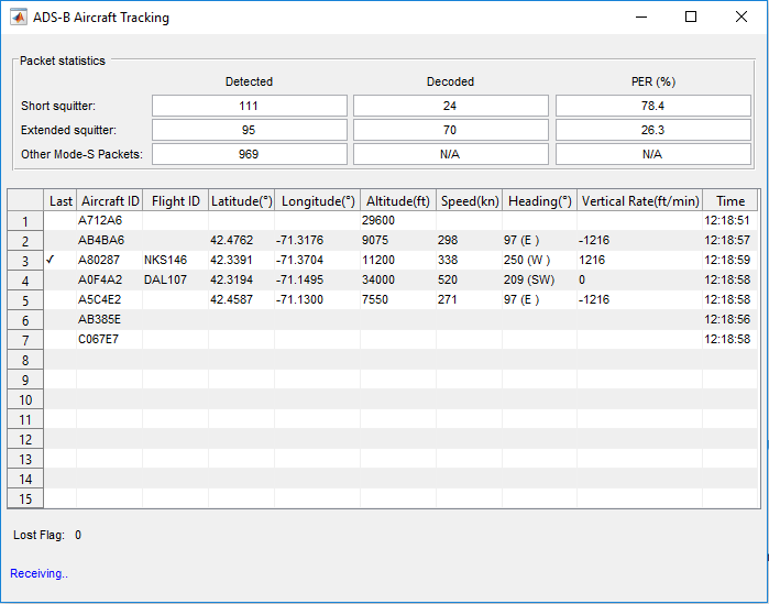
Data Viewer
The data viewer shows the received messages on a graphical user interface (GUI). For each packet type, the number of detected packets, the number of correctly decoded packets and the packet error rate (PER) is shown. As data is captured, the application lists information decoded from these messages in a tabular form.
Launch Map and Log Data
You can also launch the map and start text file logging using the two slider switches(Launch Map and Log Data).
Log Data* - When Log Data is On, it Saves the captured data in a TXT file. You can use the saved data for later for post processing.
Launch Map- When Launch Map is On, map will be launched where the tracked flights can be viewed.NOTE:You must have a valid license for the Mapping Toolbox if you want to use this feature.
The following figures illustrate how the application tracks and lists flight details and displays them on a map.

Selected Bibliography
International Civil Aviation Organization, Annex 10, Volume 4. Surveillance and Collision Avoidance Systems.
Technical Provisions For Mode S Services and Extended Squitter (Doc 9871)
You can also select a web site from the following list:
Americas
- América Latina(Español)
- Canada(English)
- United States(English)
Europe
- Belgium(English)
- Denmark(English)
- Deutschland(Deutsch)
- España(Español)
- Finland(English)
- France(Français)
- Ireland(English)
- Italia(Italiano)
- Luxembourg(English)
- Netherlands(English)
- Norway(English)
- Österreich(Deutsch)
- Portugal(English)
- Sweden(English)
- Switzerland
- United Kingdom(English)