LLR vs. Hard Decision Demodulation in Simulink
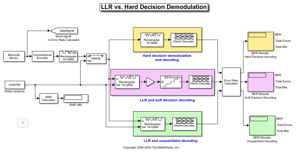
This model shows the improvement in BER performance when using log-likelihood ratio (LLR) instead of hard decision demodulation in a convolutionally coded communication link.
For a MATLAB™ version of this example, seeLog-Likelihood Ratio (LLR) Demodulation.
System Setup
This example model simulates a convolutionally coded communication system having one transmitter, an AWGN channel and three receivers. The convolutional encoder has a code rate of 1/2. The system employs a 16-QAM modulation. The modulated signal passes through an additive white Gaussian noise channel. The top receiver performs hard decision demodulation in conjunction with a Viterbi decoder that is set up to perform hard decision decoding. The second receiver has the demodulator configured to compute log-likelihood ratios (LLRs) that are then quantized using a 3-bit quantizer. It is well known that the quantization levels are dependent on noise variance for optimum performance [2]. The exact boundaries of the quantizer are empirically determined here. A Viterbi decoder that is set up for soft decision decoding processes these quantized values. The LLR values computed by the demodulator are multiplied by -1 to map them to the right quantizer index for use with Viterbi Decoder. To compute the LLR, the demodulator must be given the variance of noise as seen at its input. The third receiver includes a demodulator that computes LLRs which are processed by a Viterbi decoder that is set up in unquantized mode. The BER performance of each receiver is computed and displayed.
modelName ='commLLRvsHD'; open_system(modelName);
System Simulation and Visualization
Simulate this system over a range of information bit Eb/No values. Adjust these Eb/No values for coded bits and multi-bit symbols to get noise variance values required for the AWGN block and Rectangular QAM Baseband Demodulator block. Collect BER results for each Eb/No value and visualize the results.
EbNo = 2:0.5:8;% information rate Eb/No in dBcodeRate = 1/2;% code rate of convolutional encodernBits = 4;% number of bits in a 16-QAM symbolPavg = 10;% average signal power of a 16-QAM modulated signalsnr = EbNo - 10*log10(1/codeRate) + 10*log10(nBits);% SNR in dBnoiseVarVector = Pavg ./ (10.^(snr./10));% noise variance% Initialize variables for storing the BER resultsber_HD = zeros(1,length(EbNo)); ber_SD = zeros(1,length(EbNo)); ber_LLR = zeros(1, length(EbNo));% Loop over all noiseVarVector valuesforidx=1:length(noiseVarVector) noiseVar = noiseVarVector(idx);%#oksim(modelName);% Collect BER resultsber_HD(idx) = BER_HD(1); ber_SD(idx) = BER_SD(1); ber_LLR(idx) = BER_LLR(1);end% Perform curve fitting and plot the resultsfitBER_HD = real(berfit(EbNo,ber_HD)); fitBER_SD = real(berfit(EbNo,ber_SD)); fitBER_LLR = real(berfit(EbNo,ber_LLR)); semilogy(EbNo,ber_HD,'r*',...EbNo,ber_SD,'g*',...EbNo,ber_LLR,'b*',...EbNo,fitBER_HD,'r',...EbNo,fitBER_SD,'g',...EbNo,fitBER_LLR,'b'); legend('Hard Decision Decoding',...'Soft Decision Decoding','Unquantized Decoding'); xlabel('Eb/No (dB)'); ylabel('BER'); title('LLR vs. Hard Decision Demodulation with Viterbi Decoding'); gridon;

进一步实验有了这个系统,尝试不同ent modulation types. This system uses a binary mapped modulation scheme for faster error collection but it is well known that Gray mapped signal constellation provides better BER performance. Experiment with various constellation ordering options in the modulator and demodulator blocks. Configure the demodulator block to compute approximate LLR to see the difference in the BER performance compared to hard decision demodulation and LLR. Try out a different range of Eb/No values. Finally, investigate different quantizer boundaries for your modulation scheme and Eb/No values.
Using Dataflow in Simulink
您可以配置这个例子to use data-driven execution by setting the Domain parameter to dataflow for Dataflow Subsystem. With dataflow, blocks inside the domain, execute based on the availability of data as rather than the sample timing in Simulink. Simulink automatically partitions the system into concurrent threads. This autopartitioning accelerates simulation and increases data throughput. To learn more about dataflow and how to run this example using multiple threads, seeMulticore Simulation of Comparing Demodulation Types.
% Cleanupclose_system(modelName,0); clearmodelNameEbNocodeRatenBitsPavgsnrnoiseVarVector...ber_HDber_SDber_LLRidxnoiseVarfitBER_HDfitBER_SDfitBER_LLR;
Selected Bibliography
[1] J. L. Massey, "Coding and Modulation in Digital Communications", Proc. Int. Zurich Seminar on Digital Communications, 1974
[2] J. A. Heller, I. M. Jacobs, "Viterbi Decoding for Satellite and Space Communication", IEEE® Trans. Comm. Tech. vol COM-19, October 1971
Select a Web Site
Choose a web site to get translated content where available and see local events and offers. Based on your location, we recommend that you select:.
Selectweb siteYou can also select a web site from the following list:
Americas
- América Latina(Español)
- Canada(English)
- United States(English)
Europe
- Belgium(English)
- Denmark(English)
- Deutschland(Deutsch)
- España(Español)
- Finland(English)
- France(Français)
- Ireland(English)
- Italia(Italiano)
- Luxembourg(English)
- Netherlands(English)
- Norway(English)
- Österreich(Deutsch)
- Portugal(English)
- Sweden(English)
- Switzerland
- United Kingdom(English)