Effect of Inter-Cell Interference on PDSCH Throughput with MMSE-IRC Receiver
This example demonstrates the effect of inter-cell interference on PDSCH throughput with minimum mean square error (MMSE) and minimum mean square error - interference rejection combining (MMSE-IRC) receiver. A serving cell and two interfering eNodeBs are considered. The conditions specified in TS 36.101, Section 8.2.1.4.1B [1] are used.
Introduction
This example measures the achieved throughput for a user equipment (UE) in the serving cell with inter-cell interference from two dominant interfering cells. The serving cell uses RMC R.47 in FDD mode. The parameters for the serving and interfering cells including power levels and noise levels are described in TS 36.101, Section 8.2.1.4.1B [1].
Simulation Settings
The default simulation length is set to four frames to keep the simulation time low. IncreaseNFramesto increase the simulation time and produce statistically significant throughput results. Use the variableeqMethodto set the receiver equalization, which can take the values 'MMSE' and 'MMSE_IRC'.
NFrames = 4;% Number of frameseqMethod ='MMSE_IRC';% MMSE, MMSE_IRC
The signal, interferers, and noise power levels are specified in the test (TS 36.101, Section 8.2.1.4.1B [1]) using the following parameters: signal-to-interference-plus-noise ratio (SINR), dominant interferer proportion (DIP) and noise power spectral density.
SINR = 0.8;% SINR in dBDIP2 = -1.73;% DIP in dB for cell 2DIP3 = -8.66;% DIP in dB for cell 3Noc = -98;% dBm/15kHz average power spectral density
The DIP characterizes each of the interfering cells and is defined as:


where and
and are the average received power spectral density from cells 2 and 3, respectively.
 is the average power spectral density of a white noise source (average power per resource element normalized with respect to the subcarrier spacing).
Serving eNodeB Configuration
The test considered uses reference channel R.47 in FDD mode. The parameters associated with this reference channel are specified in (TS 36.101, Table A.3.3.2.1-2 [1]). The structureenb1characterizes the serving cell.
% Set the random number generator seedrng('default');%设置单元1eNodeB configuration according to R.47simulationParameters = struct; simulationParameters.NDLRB = 50; simulationParameters.CellRefP = 2; simulationParameters.NCellID = 0; simulationParameters.CFI = 2; simulationParameters.DuplexMode ='FDD'; simulationParameters.TotSubframes = 1;%这不是the total number of% subframes used in the simulation, just the number of subframes we% generate per call to the waveform generator.% Specify PDSCH configuration substructuresimulationParameters.PDSCH.TxScheme ='SpatialMux'; simulationParameters.PDSCH.Modulation = {'16QAM'}; simulationParameters.PDSCH.NLayers = 1; simulationParameters.PDSCH.Rho = -3; simulationParameters.PDSCH.PRBSet = (0:49)';% Table A.3.3.2.1-2, TS 36.101simulationParameters.PDSCH.TrBlkSizes = [8760 8760 8760 8760 8760 0 8760 8760 8760 8760];% Table A.3.3.2.1-2, TS 36.101simulationParameters.PDSCH.CodedTrBlkSizes = [24768 26400 26400 26400 26400 0 26400 26400 26400 26400]; simulationParameters.PDSCH.CSIMode ='PUCCH 1-1'; simulationParameters.PDSCH.PMIMode ='Wideband'; simulationParameters.PDSCH.CSI ='On'; simulationParameters.PDSCH.W = []; simulationParameters.PDSCH.CodebookSubset ='1111';% Specify PDSCH OCNG configurationsimulationParameters.OCNGPDSCHEnable ='On';% Enable OCNG fillsimulationParameters.OCNGPDSCHPower = -3;% OCNG power same as PDSCH RhosimulationParameters.OCNGPDSCH.RNTI = 0;% Virtual UE RNTIsimulationParameters.OCNGPDSCH.Modulation ='QPSK';% OCNG symbol modulationsimulationParameters.OCNGPDSCH.TxScheme ='TxDiversity';% OCNG transmission mode 2
CalllteRMCDLToolto generate the default eNodeB parameters not specified insimulationParameters.
enb1 = lteRMCDL(simulationParameters);
Interfering eNodeBs Configurations
The two interfering cells are characterized by the structuresenb2andenb3. These have the same field values as the serving cell (enb1) with the following exceptions:
Cell Id takes the values 1 and 2 for
enb2andenb3, respectively.
The PDSCH modulation scheme is specified by the transmission mode 4 (TM4) interference model (TS 36.101, B.5.3 [1]). This value changes on a subframe-by-subframe basis and is modified in the main processing loop.
% Cell 2enb2 = enb1; enb2.NCellID = 1; enb2.OCNGPDSCHEnable =“关闭”;% Cell 3enb3 = enb1; enb3.NCellID = 2; enb3.OCNGPDSCHEnable =“关闭”;
Propagation Channel and Channel Estimator Configurations
This section sets up the parameters for three propagation channels
Serving cell to UE
First interfering cell to UE
Second interfering cell to UE
As specified in (TS 36.101, Table 8.2.1.4.1B-2 [1]) EVA5 channel conditions are used.
% eNodeB1 to UE propagation channelchannel1 = struct;% Channel config structurechannel1.Seed = 20;% Channel seedchannel1.NRxAnts = 2;% 2 receive antennaschannel1.DelayProfile ='EVA';% Delay profilechannel1.DopplerFreq = 5;% Doppler frequencychannel1.MIMOCorrelation ='Low';% Multi-antenna correlationchannel1.NTerms = 16;% Oscillators used in fading modelchannel1.ModelType ='GMEDS';% Rayleigh fading model typechannel1.InitPhase ='Random';% Random initial phaseschannel1.NormalizePathGains ='On';% Normalize delay profile powerchannel1.NormalizeTxAnts ='On';% Normalize for transmit antennas
The channel sampling rate depends on the FFT size used in the OFDM modulator. This can be obtained using the functionlteOFDMInfo.
ofdmInfo = lteOFDMInfo(enb1); channel1.SamplingRate = ofdmInfo.SamplingRate;% eNodeB2 (interference) to UE propagation channelchannel2 = channel1; channel2.Seed = 122;% Channel seed% eNodeB3 (interference) to UE propagation channelchannel3 = channel1; channel3.Seed = 36;% Channel seed
The variableperfectChanEstimatorcontrols channel estimator behavior. Valid values aretrueorfalse. When set totruea perfect channel estimate is used otherwise an imperfect estimate is used, based on the values of received pilot signals.
% Channel estimator behaviorperfectChanEstimator = true;% The channel estimator configuration structure is defined below. The% frequency and time averaging window sizes are chosen to span a relatively% large number of resource elements. The large window sizes are chosen to% average as much as possible noise and interference in the resource% elements. Note that too large an averaging window in time and/or frequency% will cause loss of information due to averaging out the channel variations.% This produces an increasingly imperfect channel estimate which can affect% the performance of the equalizer.cec = struct;% Channel estimation config structurecec.PilotAverage ='UserDefined';% Type of pilot symbol averagingcec.FreqWindow = 31;% Frequency window sizecec.TimeWindow = 23;% Time window sizecec.InterpType ='Cubic';% 2D interpolation typecec.InterpWindow ='Centered';% Interpolation window typecec.InterpWinSize = 1;% Interpolation window size
Signal, Interference and Noise Power Levels
From the SINR, DIP andNocvalues we can calculate the scaling factors to apply to the signals from the serving and interfering cells, as well as the noise level.
The functionhENBscalingFactors.mcalculates the scaling factorsK1,K2andK3to apply to the channel filtered waveforms from the three cells considered. The scaling factorNo适用于高斯白噪声也没lated. These values ensure that the signal power, interference power and noise power are as per the specified SINR and DIP values.
% Channel noise setupnocLin = 10.^(Noc/10)*(1e-3);% linear in Watts% Take into account FFT (OFDM) scalingNo = sqrt(nocLin/(2*double(ofdmInfo.Nfft)));% Signal and interference amplitude scaling factors calculation[K1, K2, K3] = hENBscalingFactors(DIP2, DIP3, Noc, SINR, enb1, enb2, enb3);
Main Loop Initialization
Before the main processing loop we need to set up the hybrid automatic repeat request (HARQ) processes and initialize intermediate variables. A HARQ process ID sequence corresponding to the configuration is output by thelteRMCDLToolfunction. A HARQ process (with IDs 1 to 8) is associated to each subframe that has data scheduled. A value of 0 in the sequence indicates that data is not transmitted in the corresponding subframe. This can be because it is an uplink subframe or because no data is scheduled in a downlink subframe (similar to subframe 5 in this example).
% Initialize state of all HARQ processesharqProcesses = hNewHARQProcess(enb1);% Initialize HARQ process IDs to 1 as the first non-zero transport% block will always be transmitted using the first HARQ process. This% will be updated with the full sequence output by lteRMCDLTool after% the first call to the functionharqProcessSequence = 1;% Set up variables for the main looplastOffset = 0;% Initialize frame timing offset from previous frameframeOffset = 0;% Initialize frame timing offsetnPMI = 0;% Initialize the number of precoder matrix indication% (PMI) set calculatedblkCRC = [];% Block CRC for all considered subframesbitTput = [];% Number of successfully received bits per subframetxedTrBlkSizes = [];% Number of transmitted bits per subframes% Vector of total number of bits transmitted, calculated for each subframe.runningMaxThPut = [];% Vector storing the number of successfully received bits, calculated for% each subframe.runningSimThPut = [];% Obtain the number of transmit antennas.dims = lteDLResourceGridSize(enb1); P = dims(3);% Assign the redundancy version sequence for each codeword and transport% block sizes for each subframervSequence = enb1.PDSCH.RVSeq; trBlkSizes = enb1.PDSCH.TrBlkSizes;% Set the PMI delay for the closed-loop spatial multiplexingpmiDelay = 8;% As specified in TS 36.101, Table 8.2.1.4.1B-1% Initialize PMIs for the first 'pmiDelay' subframespmiDims = ltePMIInfo(enb1,enb1.PDSCH); txPMIs = zeros(pmiDims.NSubbands, pmiDelay);% Flag to indicate if a valid PMI feedback is available from the UEpmiReady = false;
Main Loop
The main loop iterates over the specified number of subframes. For each downlink subframe with data the following operations are performed:
Check the HARQ processes and determine whether to send a new packet or if a retransmission is required
Generate downlink waveforms from serving cell and interfering cells
Filter waveforms with propagation channels and add white Gaussian noise
Synchronize and OFDM demodulate the signal from the serving cell
Estimate the propagation channel for the serving cell
Equalize and decode the PDSCH
Decode the DL-SCH
Determine throughput performance using the block CRC obtained
fprintf('\nSimulating %d frame(s)\n',NFrames);% Main for loop: for all subframesforsubframeNo = 0:(NFrames*10-1)% Reinitialize channel seed for each subframe to increase variabilitychannel1.Seed = 1+subframeNo; channel2.Seed = 1+subframeNo+(NFrames*10); channel3.Seed = 1+subframeNo+2*(NFrames*10);% Update subframe numberenb1.NSubframe = subframeNo; enb2.NSubframe = subframeNo; enb3.NSubframe = subframeNo; duplexInfo = lteDuplexingInfo(enb1);ifduplexInfo.NSymbolsDL ~= 0% target only downlink subframes% Get HARQ process ID for the subframe from HARQ process sequenceharqID = harqProcessSequence(mod(subframeNo, length(harqProcessSequence))+1);% If there is a transport block scheduled in the current subframe% (indicated by non-zero 'harqID'), perform transmission and% reception. Otherwise, continue to the next subframe.ifharqID == 0continue;end% Update current HARQ processharqProcesses(harqID) = hHARQScheduling(...harqProcesses(harqID), subframeNo, rvSequence);% Extract the current subframe transport block size(s)trBlk = trBlkSizes(:, mod(subframeNo, 10)+1).';% Update the PDSCH transmission config with HARQ process stateenb1.PDSCH.RVSeq = harqProcesses(harqID).txConfig.RVSeq; enb1.PDSCH.RV = harqProcesses(harqID).txConfig.RV; dlschTransportBlk = harqProcesses(harqID).data;% Set the PMI to the appropriate value in the delay queueifstrcmpi(enb1.PDSCH.TxScheme,'SpatialMux') pmiIdx = mod(subframeNo, pmiDelay);% PMI index in delay queueenb1.PDSCH.PMISet = txPMIs(:, pmiIdx+1);% Set PMIend% Create transmit waveform[tx,~,enbOut] = lteRMCDLTool(enb1, dlschTransportBlk);% Pad 25 samples to cover the range of delays expected from channel% modeling (a combination of implementation delay and channel delay%传播)txWaveform1 = [tx; zeros(25, P)];% Get the HARQ ID sequence from 'enbOut' for HARQ processingharqProcessSequence = enbOut.PDSCH.HARQProcessSequence;% Generate interferer model as per as per TS 36.101, B.5.3. The% function hTM4InterfModel generates the interferer transmit signal.txWaveform2 = [hTM4InterfModel(enb2); zeros(25,P)]; txWaveform3 = [hTM4InterfModel(enb3); zeros(25,P)];% Specify channel time for the present subframechannel1.InitTime = subframeNo/1000; channel2.InitTime = channel1.InitTime; channel3.InitTime = channel1.InitTime;%通过通道传递数据rxWaveform1 = lteFadingChannel(channel1,txWaveform1); rxWaveform2 = lteFadingChannel(channel2,txWaveform2); rxWaveform3 = lteFadingChannel(channel3,txWaveform3);% Generate noisenoise = No*complex(randn(size(rxWaveform1)),...randn(size(rxWaveform1)));% Add AWGN to the received time domain waveformrxWaveform= K1*rxWaveform1 + K2*rxWaveform2 + K3*rxWaveform3 + noise;% Receiver% Once every frame, on subframe 0, calculate a new synchronization% offsetif(mod(subframeNo,10) == 0) frameOffset = lteDLFrameOffset(enb1, rxWaveform);if(frameOffset > 25) frameOffset = lastOffset;endlastOffset = frameOffset;end% Synchronize the received waveformrxWaveform= rxWaveform(1+frameOffset:end, :);% Scale rxWaveform by 1/K1 to avoid numerical issues with% channel decoding stagesrxWaveform= rxWaveform/K1;% Perform OFDM demodulation on the received data to obtain the% resource gridrxSubframe = lteOFDMDemodulate(enb1, rxWaveform);% Perform channel estimationif(perfectChanEstimator) estChannelGrid = lteDLPerfectChannelEstimate(enb1, channel1, frameOffset); noiseInterf = K2*rxWaveform2 + K3*rxWaveform3 + noise; noiseInterf = noiseInterf/K1; noiseGrid = lteOFDMDemodulate(enb1, noiseInterf(1+frameOffset:end ,:)); noiseEst = var(noiseGrid(:));else[estChannelGrid, noiseEst] = lteDLChannelEstimate(...enb1 enb1。PDSCH、cec rxSubframe);end% Get PDSCH indicespdschIndices = ltePDSCHIndices(enb1,enb1.PDSCH,enb1.PDSCH.PRBSet);% Get PDSCH resource elements. Scale the received subframe by% the PDSCH power factor Rho.[pdschRx, pdschHest] = lteExtractResources(pdschIndices,...rxSubframe*(10^(-enb1.PDSCH.Rho/20)), estChannelGrid);% Perform equalization and deprecodingifstrcmp(eqMethod,'MMSE')% MIMO equalization and deprecoding (MMSE based)[rxDeprecoded,csi] = lteEqualizeMIMO(enb1,enb1.PDSCH,...pdschRx,pdschHest,noiseEst);else% MIMO equalization and deprecoding (MMSE-IRC based)[rxDeprecoded,csi] = hEqualizeMMSEIRC(enb1,enb1.PDSCH,...rxSubframe,estChannelGrid,noiseEst);end% Perform layer demapping, demodulation and descramblingcws = ltePDSCHDecode(enb1,setfield(enb1.PDSCH,'TxScheme',...'Port7-14'),rxDeprecoded);% The PDSCH transmission scheme is% modified into port7-14, in order to skip the deprecoding operation% Scaling LLRs by CSIcws = hCSIscaling(enb1.PDSCH,cws,csi);% Decode DL-SCH[decbits, harqProcesses(harqID).blkerr,harqProcesses(harqID).decState] =...lteDLSCHDecode(enb1, enb1.PDSCH, trBlk, cws,...harqProcesses(harqID).decState);% Store values to calculate throughput% Only for subframes with data and valid PMI feedbackifany(trBlk) && pmiReady blkCRC = [blkCRC harqProcesses(harqID).blkerr]; txedTrBlkSizes = [txedTrBlkSizes trBlk]; bitTput = [bitTput trBlk.*(1-harqProcesses(harqID).blkerr)];endrunningSimThPut = [runningSimThPut sum(bitTput,2)]; runningMaxThPut = [runningMaxThPut sum(txedTrBlkSizes,2)];% Provide PMI feedback to the eNodeBifstrcmpi(enb1.PDSCH.TxScheme,'SpatialMux') PMI = ltePMISelect(enb1, enb1.PDSCH, estChannelGrid, noiseEst); txPMIs(:, pmiIdx+1) = PMI; nPMI = nPMI+1;ifnPMI>=pmiDelay pmiReady = true;endendendend
Simulating 4 frame(s)
Results
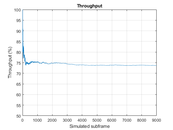
This section calculates the achieved throughput. A figure with the running measured throughput for all simulated subframes is also provided.
maxThroughput = sum(txedTrBlkSizes);% Maximum possible throughputsimThroughput = sum(bitTput,2);% Simulated throughput% Display achieved throughput percentagedisp(['Achieved throughput 'num2str(simThroughput*100/maxThroughput)'%'])% Plot running throughputfigure;plot(runningSimThPut*100./runningMaxThPut) ylabel('Throughput (%)'); xlabel('Simulated subframe'); title('Throughput');
Achieved throughput 78.5714%

For statistically valid results, the simulation should be run for a larger number of frames. The figure below shows the throughput results when simulating 1000 frames.
Appendix
This example uses the following helper functions:
Selected Bibliography
3GPP TS 36.101 "User Equipment (UE) radio transmission and reception"
3GPP TR 36.829 "Enhanced performance requirement for LTE User Equipment (UE)"
You can also select a web site from the following list:
Americas
- América Latina(Español)
- Canada(English)
- United States(English)
Europe
- Belgium(English)
- Denmark(English)
- Deutschland(Deutsch)
- España(Español)
- Finland(English)
- France(Français)
- Ireland(English)
- Italia(Italiano)
- Luxembourg(English)
- Netherlands(English)
- 挪威(English)
- Österreich(Deutsch)
- Portugal(English)
- Sweden(English)
- Switzerland
- United Kingdom(English)