Introduction to Hybrid Beamforming
this example introduces the basic concept of hybrid beamforming and shows how to simulate such a system.
Introduction
Modern wireless communication systems use spatial multiplexing to improve the data throughput within the system in a scatterer rich environment. In order to send multiple data streams through the channel, a set of precoding and combining weights are derived from the channel matrix. Then each data stream can be independently recovered. Those weights contain both magnitude and phase terms and are normally applied in the digital domain. One example of simulating such a system can be found in the提高信噪比和无线的能力sCommunication Using Antenna Arraysexample. In the system diagram shown below, each antenna is connected to a unique transmit and receive (TR) module.

the ever growing demand for high data rate and more user capacity increases the need to use the spectrum more efficiently. As a result, the next generation, 5G, wireless systems will use millimeter wave (mmWave) band to take advantage of its wider bandwidth. In addition, 5G systems deploy large scale antenna arrays to mitigate severe propagation loss in the mmWave band. However, these configurations bring their unique technical challenges.
Compared to current wireless systems, the wavelength in the mmWave band is much smaller. Although this allows an array to contain more elements with the same physical dimension, it becomes much more expensive to provide one TR module for each antenna element. Hence, as a compromise, a TR switch is often used to supply multiple antenna elements. This is the same concept as the subarray configuration used in the radar community. One such configuration is shown in the following figure.
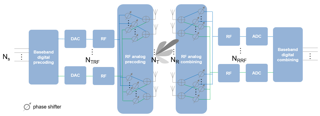
the figure above shows that on the transmit side, the number of TR switches, ,小于天线元件的数量, 。为了提供更大的灵活性,每个天线元件可以连接到一个或多个TR模块。另外,可以在每个TR模块和天线之间插入模拟相变器,以提供一些有限的转向能力。
the configuration on the receiver side is similar, as shown in the figure. The maximum number of data streams, ,,,,that can be supported by this system is the smaller of 一个d 。
In this configuration, it is no longer possible to apply digital weights on each antenna element. Instead, the digital weights can only be applied at each RF chain. At the element level, the signal is adjusted by analog phase shifters, which only changes the phase of the signal. Thus, the precoding or combining are actually done in two stages. Because this approach performs beamforming in both digital and analog domains, it is referred to as hybrid beamforming.
系统设置
本节模拟了一个64 x 16 MIMO混合横梁成形系统,具有64个元素的正方形阵列,在发射器侧有4个RF链,一个16个元素的正方形阵列在接收器侧,带有4个RF链。
NT = 64;ntrf = 4;NR = 16;nrrf = 4;
In this simulation, it is assumed that each antenna is connected to all RF chains. Thus, each antenna is connected to 4 phase shifters. Such an array can be modeled by partitioning the array aperture into 4 completely connected subarrays.
RNG(4096);C = 3E8;FC = 28E9;lambda = c/fc;txArray = phase.partitionedarray(...'Array',,,,phased.URA([sqrt(Nt) sqrt(Nt)],lambda/2),...“子阵列”,,,,ones(NtRF,Nt),'SubarraySteering',,,,'Custom');rxarray = phased.PartitionedArray(...'Array',,,,phased.URA([sqrt(Nr) sqrt(Nr)],lambda/2),...“子阵列”,,,,ones(NrRF,Nr),'SubarraySteering',,,,'Custom');
to maximize the spectral efficiency, each RF chain can be used to send an independent data stream. In this case, the system can support up to 4 streams.
next, assume a scattering environment with 6 scattering clusters randomly distributed in space. Within each cluster, there are 8 closely located scatterers with an angle spread of 5 degrees, for a total of 48 scatterers. The path gain for each scatterer is obtained from a complex circular symmetric Gaussian distribution.
ncl = 6;nray = 8;n -scatter = nray*ncl;angspread = 5;% compute randomly placed scatterer clusterstxclang = [rand(1,Ncl)*120-60;rand(1,Ncl)*60-30]; rxclang = [rand(1,Ncl)*120-60;rand(1,Ncl)*60-30]; txang = zeros(2,Nscatter); rxang = zeros(2,Nscatter);% compute the rays within each cluster为了m = 1:Ncl txang(:,(m-1)*Nray+(1:Nray)) = randn(2,Nray)*sqrt(angspread)+txclang(:,m); rxang(:,(m-1)*Nray+(1:Nray)) = randn(2,Nray)*sqrt(angspread)+rxclang(:,m);结尾g =(randn(1,n -scatter)+1i*randn(1,n -scatter))/sqrt(n -scatter);
通道矩阵可以形成为
txpos = getElementPosition(txarray)/lambda; rxpos = getElementPosition(rxarray)/lambda; H = scatteringchanmtx(txpos,rxpos,txang,rxang,g);
Hybrid Weights Computation
In a spatial multiplexing system with all digital beamforming, the signal is modulated by a set of precoding weights, propagated through the channel, and recovered by a set of combining weights. Mathematically, this process can be described byy =(x*f*h+n)*w在哪里Xis anns- 列的列矩阵,其列是数据流,Fis anns
ntmatrix representing the precoding weights,wis annr
ns代表合并权重的矩阵,nis annr- 列矩阵的列是每个元素的接收器噪声,并且yis anns圣列矩阵的列是恢复数据reams. Since the goal of the system is to achieve better spectral efficiency, obtaining the precoding and combining weights can be considered as an optimization problem where the optimal precoding and combining weights make the product off*h*w'a diagonal matrix so each data stream can be recovered independently.
在杂交边缘系统中,信号流相似。预编码的重量和组合重量都是基带数字重量和RF带模拟权重的组合。基带数字权重将传入的数据流转换为每个RF链处的输入信号,然后模拟权重将每个RF链的信号转换为每个天线元件辐射或收集的信号。请注意,模拟权重只能包含相移。
Mathematically, it can be written asF=Fbb*Frf一个dw=Wbb*Wrf,,,,在哪里Fbbis anns
ntrf矩阵,Frf一个ntrf
nt矩阵,WBB一个nrRF
ns矩阵,一个dWRF一个nr
nrRF矩阵。从两者开始Frf一个dWRF只能用于修改信号阶段,优化过程中有额外的约束,以识别最佳的预编码和合并权重。理想情况下,由此产生的组合Fbb*Frf一个dWRF*Wbbare close approximations ofF一个dwthat are obtained without those constraints.
不幸的是,同时优化所有四个矩阵变量非常困难。因此,建议许多算法以合理的计算负载来达到次优的权重。该示例使用[1]中提出的方法,该方法将预言和组合权重的优化分解。它首先使用正交匹配追踪算法来得出预编码的权重。一旦计算了预编码的权重,然后将结果用于获得相应的组合权重。
Assuming the channel is known, the unconstrained optimal precoding weights can be obtained by diagonalizing the channel matrix and extracting the firstntrfdominating modes. The transmit beam pattern can be plotted as
F= diagbfweights(H); F = F(1:NtRF,:); pattern(txarray,fc,-90:90,-90:90,'Type',,,,'efield',,,,...'ElementWeights',,,,F','PropagationSpeed',,,,c);
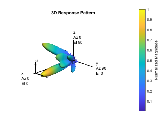
上面的响应模式表明,即使在多路径环境中,主导方向也有限。
另一方面,混合权重可以计算为
at = steervec(txpos,txang);ar = steervec(rxpos,rxang);ns= NtRF; [Fbb,Frf] = omphybweights(H,Ns,NtRF,At);
the beam pattern of the hybrid weights is shown below:
pattern(txarray,fc,-90:90,-90:90,'Type',,,,'efield',,,,...'ElementWeights',frf'*fbb','PropagationSpeed',,,,c);
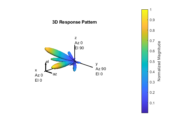
与使用最佳重量获得的光束图案相比,使用混合重量的束图案相似,尤其是对于主要的梁。这意味着可以使用混合权重通过这些梁成功传输数据流。
Spectral Efficiency Comparison
One of the system level performance metrics of a 5G system is the spectral efficiency. The next section compares the spectral efficiency achieved using the optimal weights with that of the proposed hybrid beamforming weights. The simulation assumes 1 or 2 data streams as outlined in [1]. The transmit antenna array is assumed to be at a base station, with a focused beamwidth of 60 degrees in azimuth and 20 degrees in elevation. The signal can arrive at the receive array from any direction. The resulting spectral efficiency curve is obtained from 50 Monte-Carlo trials for each SNR.
snr_param = -40:5:0;nsnr = numel(snr_param);ns_param = [1 2];nns = numel(ns_param);ntrf = 4;nrrf = 4;ropt = zeros(nsnr,nns);Rhyb =零(NSNR,NNS);niter = 50;为了m = 1:Nsnr snr = db2pow(snr_param(m));为了n = 1:NITER%通道实现txang = [rand(1,n-scatter)*60-30; rand(1,n-scatter)*20-10];rxang = [rand(1,n-scatter)*180-90; rand(1,n-scatter)*90-45];at = steervec(txpos,txang);ar = steervec(rxpos,rxang);g =(randn(1,n -scatter)+1i*randn(1,n -scatter))/sqrt(n -scatter);h = scatsingchanmtx(txpos,rxpos,txang,rxang,g);为了k = 1:nns ns = ns_param(k);% Compute optimal weights and its spectral efficiency[Fopt,Wopt] = helperOptimalHybridWeights(H,Ns,1/snr); Ropt(m,k) = Ropt(m,k)+helperComputeSpectralEfficiency(H,Fopt,Wopt,Ns,snr);% Compute hybrid weights and its spectral efficiency[FBB,FRF,WBB,WRF] = omphybweights(h,ns,ntrf,at,nrrf,ar,ar,1/snr);Rhyb(m,k)= Rhyb(M,K)+HelperComputesSpectRaleffsica(H,FBB*FRF,WRF*WBB,NS,SNR);结尾结尾结尾ropt = Ropt/Niter; Rhyb = Rhyb/Niter; plot(snr_param,Ropt(:,1),'--sr',,,,...snr_param,Ropt(:,2),'-b',,,,...snr_param,Rhyb(:,1),'-sr',,,,...snr_param,Rhyb(:,2),'-b');Xlabel('SNR (dB)');ylabel('Spectral Efficiency (bits/s/Hz');legend('Ns=1 optimal',,,,'Ns=2 optimal',,,,'Ns=1 hybrid',,,,'ns = 2混合动力',,,,...'Location',,,,'最好的');gridon;
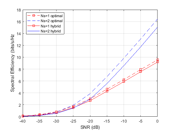
this figure shows that the spectral efficiency improves significantly when we increase the number of data streams. In addition, the hybrid beamforming can perform close to what optimal weights can offer using less hardware.
Summary
此示例介绍了混合边界的基本概念,并显示了如何使用正交匹配的追随算法分裂预编码和重量的重量。它表明,混合波束形成可以与最佳数字重量提供的性能紧密匹配。
references
[1] Omar El Ayach, et al. Spatially Sparse Precoding in Millimeter wave MIMO Systems, IEEE Transactions on Wireless Communications, Vol. 13, No. 3, March 2014.
you can also select a web site from the following list:
Americas
- América Latina(Español)
- Canada(English)
- United States(English)