Code Verification and Validation with PIL
This example shows you how to use Simulink Coder Support Package for NXP FRDM-KL25Z Board for code verification and validation using PIL. To run this model you need to have Embedded Coder Toolbox.
介绍
在此示例中,您将学习如何配置Simulink模型以运行循环的处理器(PIL)仿真。万博1manbetx在PIL模拟中,生成的代码在NXP FRDM-KL25Z板上运行。将PIL模拟的结果传输到Simulink,以验证模拟的数值等效性和代码生成结果。万博1manbetxPIL验证过程是开发周期的关键部分,以确保部署代码的行为与设计相匹配。
This example introduces the Simulink code generation and verification workflow by showing you how to:
配置模型以运行万博1manbetx模型块PILsimulations on the NXP FRDM-KL25Z board.
配置模型以运行万博1manbetxTop-Model PILsimulations on the NXP FRDM-KL25Z board.
配置模型以运行万博1manbetxPIL Blocksimulations on the NXP FRDM-KL25Z board.
Prerequisites
We recommend completingGetting Started with Simulink Coder Support Package for NXP FRDM-KL25Z Board.
Required Products
Embedded Coder
Required Hardware
To run this example you will need the following hardware:
On Mac:
NXP FRDM-KL25Z board
USB A型A到Mini-B电缆
USB TTL-232 cable - TTL-232R 3.3V
On Windows:
NXP FRDM-KL25Z board
USB A型A到Mini-B电缆
USB TTL-232 cable - TTL-232R 3.3V (This is required only when you use UART1 or UART2 serial communication interface)
Note:
This example is tested with theFTDI FriendUSB TTL-232R 3.3V adapter.
OS Specific Limitations
On Mac:
External mode simulation is supported only through UART1 or UART2.
On Windows:
External mode simulation is supported through all UART communication interfaces.
Task 1 - Choose a Serial Communication Interface for PIL Simulation
这Simulink Coder Support Package for NXP FRDM-KL25Z Board supports three different serial communication interfaces for PIL: UART0, UART1, and UART2. Please note that, on Mac platforms, PIL simulation over UART0 is supported only on Mac version 'El Capitan'.
这UART0 serial communication interface is accessible through either the mini USB port labeled withopenSDAon the NXP FRDM-KL25Z board or the onboard GPIO pins for UART0 . Using UART0 via the mini USB port does not require any additional cables or hardware, besides a USB type A to Mini-B cable that is used to connect the NXP FRDM-KL25Z board to the host computer. To use the UART0 through the other GPIO pins on NXP FRDM-KL25Z board, additional hardware, for example, a USB TTL-232R adapter.
这UART1 and UART2 serial communication interfaces are accessible only through pins on the NXP FRDM-KL25Z board. Using these interfaces requires additional hardware, for example, a USB TTL-232R adapter, to perform PIL simulations.
1.Choose a serial communication interface using the steps below:
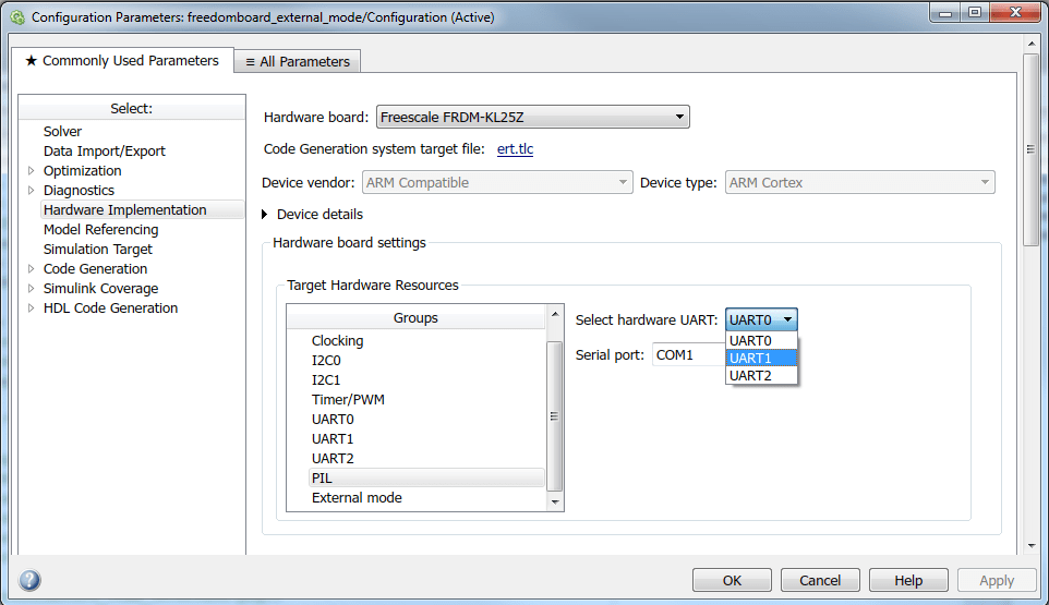
打开在NXP FRDM-KL25Z板上配置为代码生成的模型。在IN中选择UART0或UART1或UART2Configuration Parameters > Hardware Implementation > Target Hardware Resources > PIL > Select hardware UARTto choose the serial communication interface.
例如,请参见PIL Blockmodel as shown below.
2.Choose the Tx and Rx GPIO pins for the selected serial communication interface:
Once the serial communication interface is selected, choose the pins for the selected UART inConfiguration Parameters > Hardware Implementation > Target Hardware Resources > 'Selected Target UART in step 2 above'.
As an example for UART1, see the settings in thePIL Blockmodel as shown below.

3.Connect to the hardware. Follow the steps below based on the serial interface you selected:
For UART0:
Connect a USB cable from your computer to the OpenSDA mini-B USB connector of the NXP FRDM-KL25Z Board.
如果为UART0选择的TX引脚是PTE20或者PTD7, connect the RX pin of the USB TTL-232R adapter to the selected TX pin on the NXP FRDM-KL25Z board. However, if the TX pin selected for UART0 isPTA2 (USBTX), then the USB cable from your computer to the OpenSDA mini-B USB connector of the NXP FRDM-KL25Z Board is enough.
If the RX Pin selected for UART0 is eitherPTE21或者PTD6,将USB TTL-232R适配器的TX引脚连接到NXP FRDM-KL25Z板上的选定RX PIN。但是,如果为UART0选择的RX引脚为PTA1(USBRX), then the USB cable from your computer to the OpenSDA mini-B USB connector of the NXP FRDM-KL25Z Board is enough.
For UART1:
Connect a USB cable from your computer to the OpenSDA mini-B USB connector of the NXP FRDM-KL25Z Board.
Connect ground pin of the USB TTL-232R adapter to one of theGNDpins on the NXP FRDM-KL25Z board
Connect the RX pin of the USB TTL-232R adapter to the TX pin, selected in Configuration Parameters for UART1, on the NXP FRDM-KL25Z board
Connect the TX pin of the USB TTL-232R adapter to the RX pin, selected in Configuration Parameters for UART1, on the NXP FRDM-KL25Z board
Connect the USB side of the USB TTL-232R adapter to your host computer
For UART2:
Connect a USB cable from your computer to the OpenSDA mini-B USB connector of the NXP FRDM-KL25Z Board.
Connect ground pin of the USB TTL-232R adapter to one of theGNDpins on the NXP FRDM-KL25Z board
将USB TTL-232R适配器的RX引脚连接到TX PIN,在NXP FRDM-KL25Z板上在UART2的配置参数中选择
Connect the TX pin of the USB TTL-232R adapter to the RX pin, selected in Configuration Parameters for UART2, on the NXP FRDM-KL25Z board
Connect the USB side of the USB TTL-232R adapter to your host computer
4.Once you complete the steps above, a new serial COM port should be available for use on your host computer. To find the COM port associated with your adapter cable, follow the steps below:
On Windows:
Open Device Manager
Expand the Ports Tab
If you have chosenUART1或者UART2for serial PIL communication interface, note down the COM port associated with USB TTL-232R Adapter.
If you have chosenUART0for serial external mode communication interface, and selected PTA2(USBTX) and PTA1(USBRX) for the TX and RX pins respectively, note down theOpenSDACOM port associated with NXP FRDM-KL25Z board by following steps described in the sectionInstall Drivers for NXP FRDM-KL25Z Board.
If you have chosenUART0对于串行外部模式通信接口,以及为其选择的TX和RX引脚分别是PTA2(USBTX)和PTA1(USBRX),请记下与USB TTL-232R适配器相关的COM端口。
On Mac:
Runls /dev/cu.*command in a Terminal window.
Note down the serial port name associated with the USB TTL-232R Adapter.
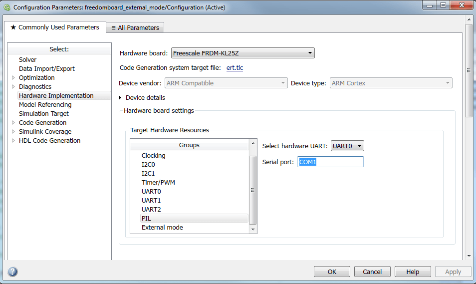
5.打开在NXP FRDM-KL25Z板上配置为代码生成的模型。In配置参数>硬件实现>目标硬件资源> PIL>串行端口, enter theSerial port在上一步中指出的带有COM端口号的字段。
例如,在Windows上输入COM27在里面Serial portfield, while on Mac enter/Dev/cu.usbmodem1442.
open_system('freedomboard_pil_block');

Task 2 - Verify the generated code for a subsystem using a PIL block
This example shows how to use a PIL block for subsystem code verification. With this approach:
您可以验证为子系统生成的代码
You must provide a test harness model to supply a test vector or stimulus inputs
You must swap your original subsystem with a generated PIL block; you should be careful to avoid saving your model in this state as you would lose your original subsystem
1.Open thePIL Blockmodel. This model is configured for theNXP FRDM-KL25Ztarget. The objective here is to create a PIL block out of theControllersubsystem that you will run on the NXP FRDM-KL25Z board.
2.Choose a PIL communication interface by following the steps inTask 1 - Choose a Serial Communication Interface for PIL Simulationof this example.
3.请按照以下步骤启用PIL:
Note: 确保这件事使用嵌入式编码器功能is enabled underHardware Implementation>Advanced parameters
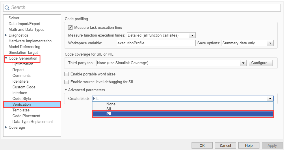
一个。去Modeling标签和按ctrl+eto open Configuration Parameters dialog box.
bGo toCode Generation>Verification>Advanced parameters和selectPIL.
4.请按照以下步骤为其创建一个PIL块Controllersubsystem:
一个。右键单击Controllersubsystem and selectDeploy this Subsystem to Hardware.

b.在里面建造code for SubsystemController对话框,单击建造.

5.Follow the below steps to run the PIL simulation:

6.You can switch between the original and PIL block subsystems by double clicking on theManual Switchblock. Double click on theNumerical Differencesblock to see the difference between the simulatedControllersubsystem and the PIL block running on the NXP FRDM-KL25Z board.
open_system('freedomboard_model_pil_block');

任务3-使用PIL验证引用的模型代码
此示例显示了如何通过运行PIL模拟来验证引用模型的生成代码。使用这种方法:
You can verify code generated for referenced models
You must provide a test harness model to provide a test vector or stimulus inputs
You can easily switch a Model block between normal and PIL simulation mode
1.Open the模型块PILmodel. This model is configured forNXP FRDM-KL25Ztarget. The model contains two Model blocks that both point at the same referenced model. You will configure one of the Model blocks to run in PIL simulation mode and the other in normal mode.
2.Choose a PIL serial communication interface for the模型块PIL和Referenced model通过遵循步骤Task 1 - Choose a Serial Communication Interface for PIL Simulationin this example.
3.Follow the below steps to configure and run theCounterAModel block in PIL mode:
一个。右键单击块CounterA和select块参数(模型Reference)

b.在里面CounterAblock parameter, Select仿真模式as循环处理器(PIL)

c.Go to模拟tab andRun
4.When the model starts running,Scope1displays the PIL simulation output running on the NXP FRDM-KL25Z board whileScope2shows the normal mode simulation output.
open_system('freedomboard_top_model_pil');
Task 4 - Verify top model code using PIL
This example shows how to verify the generated code for a model by running a PIL simulation. With this approach:
You can verify code generated for a top model
You must configure the model to load test vectors or stimulus inputs from the MATLAB workspace
You can easily switch the entire model between normal and PIL simulation mode
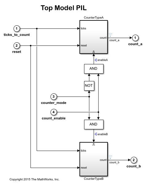
1.Open theTop Model PILmodel. This model is configured for theFreecale FRDM-KL25Ztarget.
2.Choose a PIL serial communication interface by following the steps inTask 1 - Choose a Serial Communication Interface for PIL Simulationin this example.
3.Go toApps标签和搜索SIL/PIL.

4.Select循环处理器(PIL)from theSIL/PILModedrop-down and clickRun Verification.
5.PIL模拟完成后,logsOut在基本工作区中创建变量。这logsOutdata contains PIL simulation results. You can access the logged data for signalscount_a和count_busing the following commands:
count_a = get(logsOut,'count_a');
count_a.Values.Data
count_b = get(logsOut,'count_b');
count_b.Values.Data
您还可以从以下列表中选择一个网站:
Americas
- AméricaLatina(Español)
- Canada(English)
- United States(English)
欧洲
- Belgium(English)
- 丹麦(English)
- Deutschland(德意志)
- España(Español)
- Finland(English)
- 法国(Français)
- 爱尔兰(English)
- Italia(Italiano)
- Luxembourg(English)
- Netherlands(English)
- 挪威(English)
- Österreich(德意志)
- Portugal(English)
- Sweden(English)
- Switzerland
- United Kingdom(English)