Get Started with J1939 Communication in Simulink
This example shows you how to use J1939 blocks to directly send and receive Parameter Group (PG) messages in Simulink.
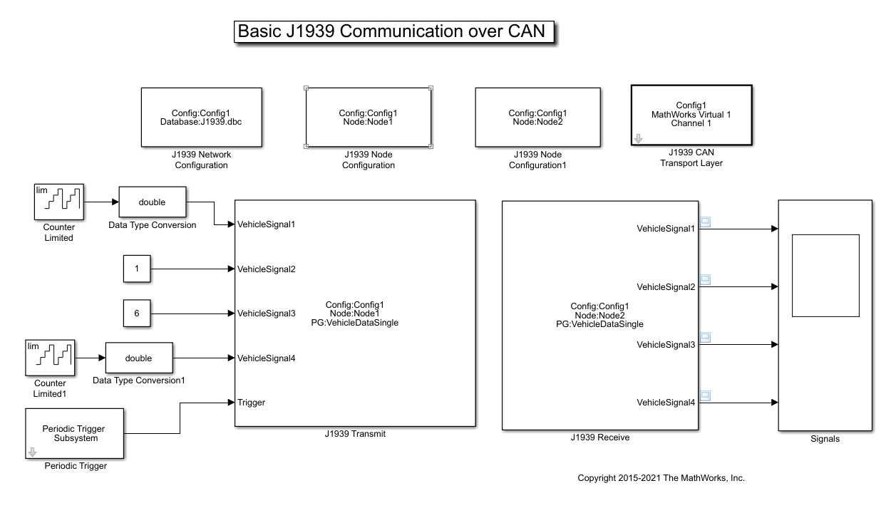
Vehicle Network Toolbox provides J1939 Simulink blocks for receiving and transmitting Parameter Groups via Simulink models over Controller Area Networks (CAN). This example performs data transfer over a CAN bus using theJ1939 Network Configuration,J1939 Node Configuration,J1939 CAN Transport Layer,J1939 TransmitandJ1939 Receiveblocks. It also uses MathWorks virtual CAN channels connected in a loopback configuration.
Set Up J1939 Block Parameters
Create a model to set up J1939 receive and transmit over the network. The model is configured to perform single frame transmission between two nodes defined in the J1939 DBC-file.
Use aJ1939 Network Configurationblock and select file
J1939.dbc. This J1939 database file consists of two nodes and a couple of single-frame and multiframe messages.Use aJ1939 CAN Transport Layerblock and set the Device to MathWorks virtual channel 1. The transport layer is configured to transfer J1939 messages over CAN via the specified virtual channel.
Use basic Simulink source blocks to connect to aJ1939 Transmitblock. The J1939 Transmit block is set to queue data for transmit at each timestep when the Trigger port is enabled. For this example, a periodic trigger subsystem sends a high pulse every 50 milliseconds.
Use theJ1939 Receiveblock to receive the messages transmitted over the network.
Visualize Signals Received on the Network
Plot the results to see the vehicle signal values received over the network. The X-axis corresponds to the simulation timestep.

Select a Web Site
Choose a web site to get translated content where available and see local events and offers. Based on your location, we recommend that you select:.
Selectweb siteYou can also select a web site from the following list:
Americas
- América Latina(Español)
- Canada(English)
- United States(English)
Europe
- Belgium(English)
- Denmark(English)
- Deutschland(Deutsch)
- España(Español)
- Finland(English)
- France(Français)
- Ireland(English)
- Italia(Italiano)
- Luxembourg(English)
- Netherlands(English)
- Norway(English)
- Österreich(Deutsch)
- Portugal(English)
- Sweden(English)
- Switzerland
- United Kingdom(English)