使用CSI-RS的NR通道估计
此示例显示了如何生成给定载体和CSI-RS资源配置的通道状态信息参考信号(CSI-RS)符号和索引,如TS 38.211第7.4.4.1.5节中所定义。该示例显示了如何将生成的符号映射到载体资源网格,在接收器端执行通道估计,并将估计的通道与实际通道进行比较。
介绍
CSI-RS是一个下行链路特异性(DL)参考信号。NR标准定义零功率(ZP)和非零功率(NZP)CSI-RSS。
用户设备(UE)处理使用NZP-CSI-RSS:
L1引用信号接收功率(RSRP)测量用于移动性和光束管理
DL CSI收购
干扰测量
时间和频率跟踪
ZP-CSI-RS用于DL CSI采集和干扰测量。它还掩盖了某些资源元素(RES),使其无法用于PDSCH传输。如ZP所示的名称,其中没有任何内容。
此示例显示了如何使用CSI-RS执行构成CSI采集基础的通道估计。
初始化配置对象
创建一个代表5 MHz载体的载体配置对象,其子载波间距为15 kHz。
载体= nrCarrierConfig;凯莉r.NSizeGrid = 25; carrier.SubcarrierSpacing = 15; carrier.NSlot = 1; carrier.NFrame = 0
载体=带有属性的nrcarrierConfig:ncellid:1子级别式空间:15 Cyclicprefix:'normal''''nsizeGrid:25 nSizeGrid:0 nslot:0 nslot:1 nframe:1 nframe:0读取属性:symbomSperssperslot:14 slotspersubframe:1 slotsubframe:1 slotsubframe:10 slotsperframe:10 slotsperframe:10
创建一个代表两个CSI-RS资源的CSI-RS配置对象,NZP具有第3行和ZP,并带有第5行5。
csirs = nrcsirsconfig;csirs.csirstype = {'NZP',,,,'ZP'};csirs.csirsperiod = {[5 1],[5 1]};csirs.density = {'一',,,,'一'};csirs.RowNumber = [3 5]; csirs.SymbolLocations = {1,6}; csirs.SubcarrierLocations = {6,4}; csirs.NumRB = 25
csirs =具有属性的nrcsirsconfig:csirstype:{'nzp'zp'} csirsperiod:{[5 1] [5 1]} rownumber:[3 5]密度:{'One'One'One'One''} Symbolacations:{[1] {[1][6]} subCarrierLocations:{[6] [4]} numrb:25 rboffset:0 nid:0读取属性:numcsirsports:[2 4] cdmtype:{'fd-cdm2''fd-cdm2''fd-cdm2'}'}
考虑DB中CSI-RS的功率缩放。
PowerCsirs = 0;disp([[“ CSI-RS功率缩放:”num2str(PowerCsirs)' D b');
CSI-RS功率缩放:0 dB
生成CSI-RS符号和索引
Generate CSI-RS symbols for the specified carrier and CSI-RS configuration parameters. Apply power scaling.
sym = nrCSIRS(carrier,csirs); csirsSym = sym*db2mag(powerCSIRS);
变量csirssym是包含CSI-RS符号的列向量。
为指定的载体和CSI-RS配置参数生成CSI-RS索引。
csirsind = nrcsirsindices(载体,csirs);
变量Csirsind也是与大小相同的列向量csirssym。
当您配置ZP和NZP资源时,ZP信号的生成比生成NZP信号优先。
初始化载波网格
初始化一个插槽的载波资源网格。
ports = max(csirs.numcsirsports);% Number of antenna portstxgrid = nrresourcegrid(载波,端口);
将CSI-RS符号映射到载波网格
Perform resource element mapping.
txgrid(csirsind)= csirssym;
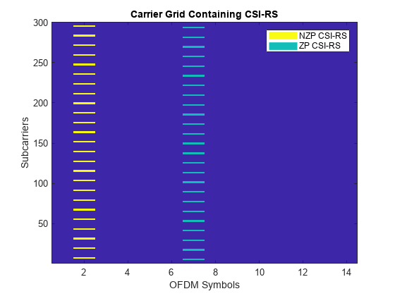
Plot the locations of the CSI-RS (both ZP and NZP) in the grid.
plotGrid(size(txGrid),csirsInd,csirsSym);
执行OFDM调制
执行OFDM调制以生成时间域波形。
[txwaveform,ofdminfo] = nrofdmmodulate(载体,txgrid);
Pass Time-Domain Waveform Through Channel and Add AWGN Noise
Configure the number of receiving antennas.
r = 4;
配置通道。
通道= nrtdlchannel;channel.numtransmitantennas = ports;channel.numreceiveantennas = r;channel.delayprofile ='TDL-C';channel.maximumdopplershift = 10;channel.delayspread = 1e-8
channel = nrTDLChannel with properties: DelayProfile: 'TDL-C' DelaySpread: 1.0000e-08 MaximumDopplerShift: 10 SampleRate: 30720000 MIMOCorrelation: 'Low' Polarization: 'Co-Polar' TransmissionDirection: 'Downlink' NumTransmitAntennas: 4 NumReceiveAntennas: 4 NormalizePathGains:真实初始时间:0 numsinusoids:48 Randomstream:'MT19937AR与种子'种子:73 normalizechannelOutputs:true channelfiltering:true transmitMiteMiteMiteMiteMmiteNdReceives wppapped:false:false
基于配置的通道,将零附加到传输波形上以解释频道延迟。
chinfo = info(channel);maxchdelay = ceil(max(chinfo.pathdelays*channel.samplerate)) + chinfo.channelfilterdelay;txwaveform = [txwaveform;零(maxchdelay,size(txwaveform,2))];
通过通道传递波形。
[rxwaveform,pathgains] =通道(txwaveform);
产生实际的传播渠道h_actual,执行完美的频道估计。
pathFilters = getPathFilters(channel); H_actual = nrPerfectChannelEstimate(carrier,pathGains,pathFilters);
Add AWGN noise to the waveform. For an explanation of the SNR definition that this example uses, see链接模拟中使用的SNR定义。
snrdb = 50;DB中的%snr = 10^(SNRDB/10);线性值%n0 = 1/sqrt(2.0*r*double(ofdminfo.nfft)*snr);% Noise varianceRNG(0);噪声= n0*复杂(randn(size(rxwaveform))),randn(size(rxwaveform)));rxwaveform = rxwaveform +噪声;
使用NZP-CSI-RS执行定时同步。要估计正时偏移,请使用nrtimingestimate并将NZP-CSI-RS视为参考。
%禁用ZP-CSI-RS资源,不用于定时和渠道估计百分比csirs.csirsperiod = {[5 1],,'离开'};%生成参考符号并应用功率缩放refsym = db2mag(powercsirs)*nrcsirs(载体,csirs);%生成参考指数refInd = nrCSIRSIndices(carrier,csirs); offset = nrTimingEstimate(carrier,rxWaveform,refInd,refSym)
偏移= 7
rxwaveform = rxwaveform(1+偏移:end,:);
OFDM解码接收到的时间域波形。
rxGrid = nrofdmdemeDemulate(载波,rxwaveform);% Of size K-by-L-by-R
比较估计的渠道与实际渠道
使用NZP-CSI-RS执行实用的通道估计。确保CSI-RS符号csirssym是相同的CDM类型。
cdmlen = [2 1];%对应于cdmtype ='fd-cdm2'[h_est,nvar] = nrChannElestimate(载体,rxgrid,Refind,refsym,“ cdmlengths',,,,cdmLen); estSNR = -10*log10(nVar); disp(['估计的snr ='num2str(estsnr)' D b')))
估计SNR = 27.4577 dB
绘制第一次传输天线和首次接收天线之间的估计通道和实际通道。
数字;%绘制估计通道subplot(1,2,1) imagesc(abs(H_est(:,:,1,1))); colorbar; title(“估计渠道”)轴xy;Xlabel(“ OFDM符号”);ylabel(“子载体”);%绘制实际渠道子图(1,2,2)imagesc(abs(h_actual(:,:::,1,1)));配色栏;标题(“实际渠道”)轴xy;Xlabel(“ OFDM符号”);ylabel(“子载体”);
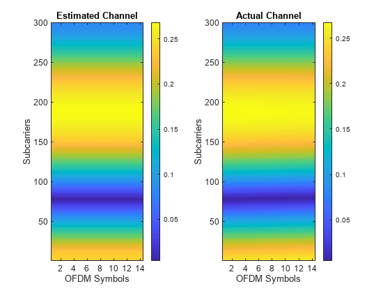
计算通道估计误差。
h_err =(h_est -h_actual(:,:,:,:,1:size(h_est,4)));[minerr,maxerr] =界限(abs(h_err),,'全部');disp([['通道估计误差的绝对值在['num2str(minErr)', 'num2str(maxerr)']')))
通道估计误差的绝对值在[4.9184e-06,0.035047]的范围内
本地功能
功能plotgrid(网格大小,csirsind,csirssym)%plotgrid(网格大小,csirsind,csirssym)绘制尺寸网格的载体网格% by populating the grid with CSI-RS symbols using CSIRSIND and CSIRSSYM.figure() cmap = colormap(gcf); chpval = {20,2}; chpscale = 0.25*length(cmap);%缩放系数tempsym = csirssym;tempsym(tempsym〜 = 0)= chpval {1};%替换非零功率符号tempsym(tempsym == 0)= chpval {2};%更换零功率符号tempgrid = complex(Zeros(GridSize));tempgrid(csirsind)= tempsym;图像(chpscale*tempgrid(:,::,1));%乘以缩放系数以获得更好的可视化轴xy;名称= {'NZP CSI-RS',,,,'ZP CSI-RS'};clevels = chpscale*[chpval {:}];n =长度(Clevels);l =线(一个(n),一个(n),'行宽',8);%生成线路%索引颜色图并将所选颜色与线路相关联set(l,{'颜色'},mat2cell(cmap(min(1+clevels,长度(cmap)),:),一个(1,n),3));% Set the colors according to cmap%创建传奇传奇(名称{:});标题(“包含CSI-RS的载体网格”) xlabel(“ OFDM符号”);ylabel(“子载体”);结尾
References
[1]3GPP TS 38.211。“ nr;物理渠道和调制。”第三代合伙项目;技术规格组无线电访问网络。
也可以看看
功能
对象
Related Topics
您还可以从以下列表中选择一个网站:
美洲
- América Latina(Español)
- 加拿大(英语)
- 美国(英语)