RF Budget Analyzer
Analyze gain, noise figure, IP2, and IP3 of cascaded RF elements and export toRF Blockset
Open the RF Budget Analyzer App
MATLAB Toolstrip: On theAppstab, underSignal Processing and Communications, click the app icon.
MATLAB command prompt: Enter
rfBudgetAnalyzer.
Examples
RF Transmitter System Analysis
Design and analyze an RF transmitter using theRF Budget Analyzerapp.
EnterrfBudgetAnalyzer打开应用程序。
Use theTransmittertemplate to create a basic transmitter.
![]()
发射机模板显示如下。
![]()
InSystem Parameters, specify the RF transmitter requirements:
Input Frequency—
815MHzAvailable Input Power—
0dBmSignal Bandwidth—
100MHz
![]()
Click theIFAmplifierin the design canvas. Delete it using theDelete Elementbutton on the toolstrip.
Add aGenericelement in the place of theIFAmplifierusing the toolstrip. In theElement Parameterspane, specify:
Name—
IFFilterAvailable Power Gain—
-3.6dBSelectApply.
Click theModulatorelement. In theElement Parameterspane, specify:
Name—
MixerAvailable Power Gain—
-6.5dBOIP3—
11.5dBmLO Frequency—
4.97GHzConverter Type—
UpSelectApply.
Delete theS-Parameterselement namedBandpassFilter. Add aGenericelement. In theElement Parameterspane, specify:
Name—
RFFilter1Available Power Gain—
-1.4dBSelectApply.
Select thePowerAmplifierelement and in theElement Parameterspane, specify:
Name—
PowerAmplifier1Available Power Gain—
20dBOIP3—
43dBmSelectApply.
Add anotherAmplifierelement using the toolstrip. In theElement Parameterspane, specify:
Name—
PowerAmplifier2Available Power Gain—
20dBOIP3—
43dBmSelectApply.
Add anotherGenericelement. In theElement Parameterspane, specify:
Name—
RFFilter2Available Power Gain—
-1.4dBSelectApply.
![]()
Save the system. The app saves the system in a MAT file.
Plot the output power of the transmitter using the3D Plotbutton. Select3D Plotand chooseOutput Power - Pout.
![]()
使用传输天线射频发射机的设计
This example uses an RF transmitter design from theRF Transmitter System Analysisexample.
Follow the RF Transmitter System Analysis example to design an RF transmitter. Select the antenna element from theElementssection and add the element at end of this RF transmitter. In theElement Parameterspane, selectAntenna Designerfrom theAntenna Sourcedrop-down list.
![]()
ClickCreate Antennain theElement Parameterspane.
![]()
TheAntenna Designerapp opens. ClickNewto explore the antenna library. This example uses adipoleFoldedantenna element with a center frequency of815MHz. To do this, selectFoldedelement from theAntenna Gallery, setDesign Frequencyto815MHz, and clickAccept.
![]()
The updated antenna shows in the window.
![]()
ClickUpdate Elementto update theAntennaelement in theRF Budget Analyzerapp. ClickOKin the Confirm Update dialog box.
![]()
TheAntenna Designerapp window closes and theAntennaelement is updated in theRF Budget Analyzerapp. TheResultspane is automatically updated for Friis analysis withEIRPandDirectivityof theAntennaelement.
![]()
RF Receiver System Analysis
Design and analyze an RF receiver using theRF Budget Analyzerapp.
EnterrfBudgetAnalyzer打开应用程序。
Use theReceivertemplate option to create a basic receiver.
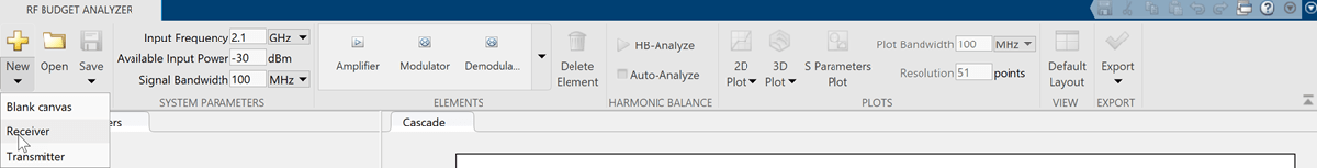
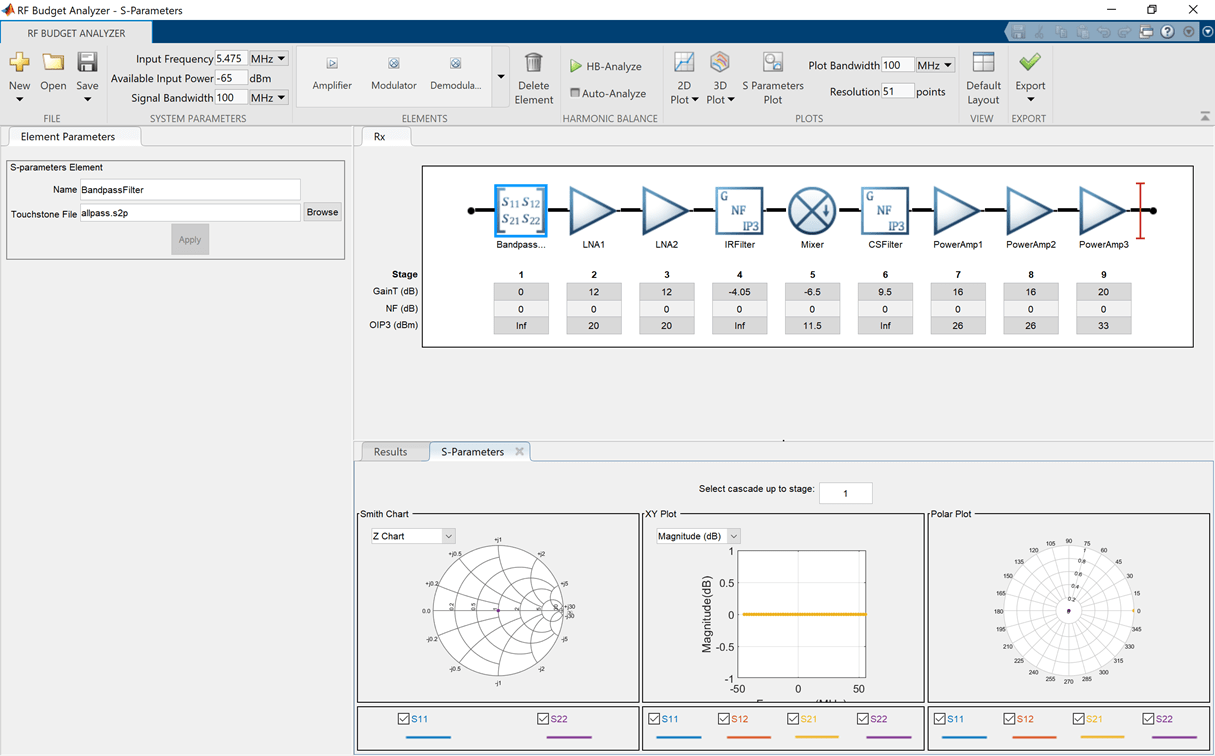
The receiver template is displayed as follows:
InSystem Parameters, specify the RF receiver requirements:
Input Frequency—
5.745MHzAvailable Input Power—
-65dBmSignal Bandwidth—
100MHz

ClickRFFilterin the design canvas. ThisRFFilteris anS-parameterselement. It accepts a Touchstone® file in the S2P file type. Update theElement parameterspane as follows:
Name:
BandpassFilterS2P file:Choose an S2P file by clicking theBrowsebutton.
SelectApply.
Click theRFAmplifierelement. In theElement Parameterspane, specify the element requirements:
Name—
LNA1Available Power Gain—
12dBOIP3—
20dBmSelectApply.
Add anotherAmplifierelement using the toolstrip. In theElement Parameterspane, specify the element requirements:
Name—
LNA2Available Power Gain—
12dBOIP3—
20dBmSelectApply.
Add aGenericelement. In theElement Parameterspane, specify the element requirements:
Name—
IRFilterAvailable Power Gain—
-4.05dBSelectApply.
Click theDemodulatorelement. In theElement Parameterspane, specify the element requirements:
Name—
MixerAvailable Power Gain—
-6.5dBOIP3—
11.5dBmLO Frequency—
4.93GHzConverter Type—
DownSelectApply.
Delete theIFFilter,S-parameterselement. Add aGenericelement in its place. In theElement Parameterspane, specify the element requirements:
Name—
CSFilterAvailable Power Gain—
-9.55dBSelectApply.
Click theIFAmplifierelement. In theElement Parameterspane, specify the element requirements:
Name—
PowerAmp1Available Power Gain—
16dBOIP3—
26dBmSelectApply.
Add two moreAmplifierelements. For each element, in theElement Parameterspanes specify the element requirements:
Name—
PowerAmp2|PowerAmp3Available Power Gain—
16dB |20dBOIP3—
26dBm |33dBmSelectApply.

Save the system. The app saves the system in a MAT file.
Plot the output OIP3 of the receiver using the3D Plotbutton. Select the3D Plotbutton and chooseOutput Third-Order Intercept Point - OIP3.

Compare Friis and Harmonic Balance Solver
Create an amplifier with a gain of 4 dB.
a = amplifier('Gain',4);
Create a modulator with an OIP3 of 13 dBm.
m = modulator('OIP3',13);
Create annportusingpassive.s2p.
n = nport('passive.s2p');
Create an RF element with a gain of 10 dB.
r = rfelement('Gain',10);
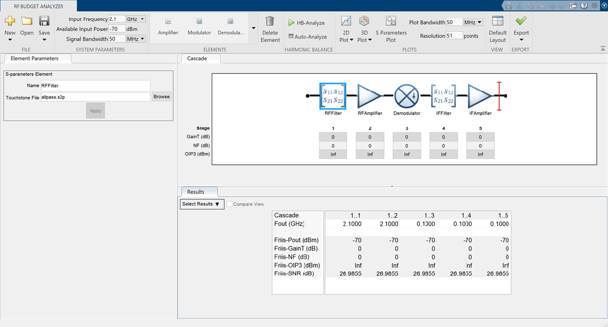
计算rfbudgetof a series of RF elements at an input frequency of 2.1 GHz, an available input power of -30 dBm, and a bandwidth of 10 MHz.
b = rfbudget([a m r n],2.1e9,-30,10e6);
Run this command in the command window, to open the system inRF Budget Analyzerapp.
show(b)

SetOIP2value ofAmplifierto60dBm usingElements Parameterspane and selectApply. InSystem Parameterssection, set theAvailable Input Powerto50dBm and run harmonic balance analysis usingHB-Analyzebutton.
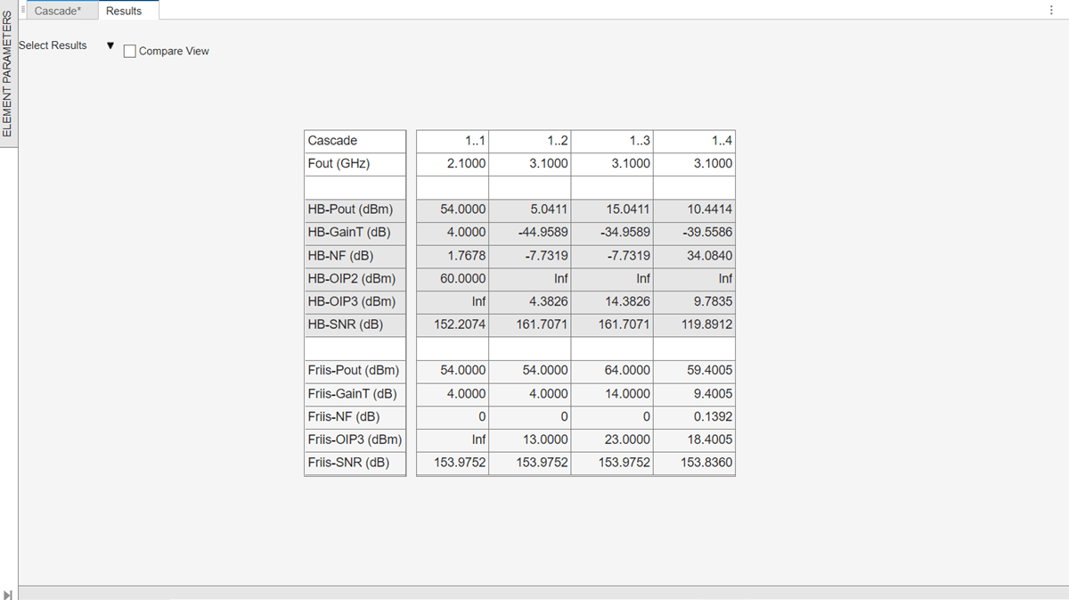
The results are displayed as shown below.
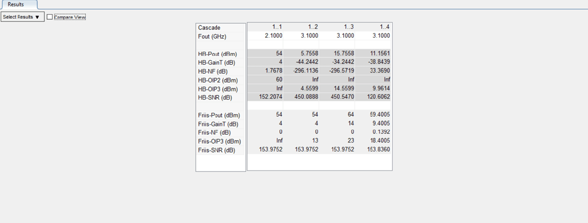
SelectAuto-Analyzecheckbox to automatically recompute the harmonic balance analysis calculations.

SetOIP2value ofRFelementas50dBm usingElements Parameterspane and selectApply.
SelectCompare Viewcheckbox in theResultspane to compare the calculated Friis and harmonic balance solver results. You can useSelect Resultsdrop-down from theResultspane to filter the results and to compare between Friis and harmonic balance solver.

Design Input Matching Network Using Transmission Line Element
Design an input matching network for a two-stage amplifier using theTransmission Lineelement in theRF Budget Analyzerapp.
EnterrfBudgetAnalyzer打开应用程序。
InSystem Parameters, specify the requirements:
Input Frequency—
2.45GHzAvailable Input Power—
0dBmSignal Bandwidth—
2GHz
![]()
Add twoTransmission Lineelements. In theElement Parameterspane, specify:
Name—
Microstrip1|Microstrip2Type—
microstrip|microstripWidth—
0.0034173|0.0034173metersHeight—
0.001524|0.001524metersThickness—
3.5e-06|3.5e-06metersEpsilonR—
3.48|3.48LossTangent—
0.0037|0.0037metersSigmaCond—
Inf|InfS/mLineLength—
0.0089|0.0147metersStubMode—
Shunt|NotAStubTermination—
OpenSelectApply.
Add twoS-Parameterselements. In theElement Parameterspane, specify:
Name—
Sparams1|Sparams2
Load the Touchstone® file (f551432p.s2p) to theS-Parameterselements provided in this example and selectApply.
![]()
Plot the input reflection coefficient of the system using the3D Plotbutton. Select the3D Plotbutton, chooseS-Parametersand selectS11.
![]()
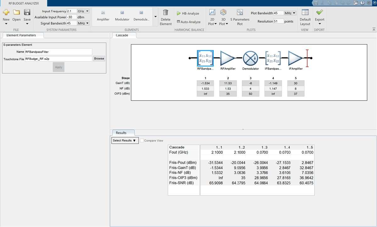
Plot S-Parameters, Output Power, and Transducer Gain of RF System
Design an RF system and plot S-parameters, output power, and transducer gain usingRF Budget Analyzerapp.
EnterrfBudgetAnalyzer打开应用程序。
InSystem Parameters, specify the requirements:
Input Frequency—
2.1GHzAvailable Input Power—
-30dBmSignal Bandwidth—
45MHz
Add aS-Parameterselement. In theElement Parameters, specify:
Name—
RFBandpassFilter
Load the Touchstone® file (RFBudget_RF.s2p) to theS-Parameterselement provided in this example and selectApply.
Add anAmplifierelement. In theElement Parameters, specify:
Name—
RFAmplifierAvailable Power Gain—
11.53dBNF—
1.53dBOIP3—
35dBmSelectApply.
Add theDemodulatorelement. In theElement Parameters, specify:
Name—
DemodulatorAvailable Power Gain—
-6dBNF —
4dBOIP3—
50dBmLO Frequency—
2.03GHzConverter Type—
DownSelectApply.
Add anotherS-Parameterselement. In theElement Parameters, specify:
Name—
IFBandpassFilter
Load the Touchstone file (RFBudget_IF.s2p) to theS-Parameterselement provided in this example and selectApply.
Add anotherAmplifierelement. In theElement Parameters, specify:
Name—
IFAmplifierAvailable Power Gain—
30dBNF—
8dBOIP3—
37dBmSelectApply.
Save the system. The app saves the system in a MAT file.
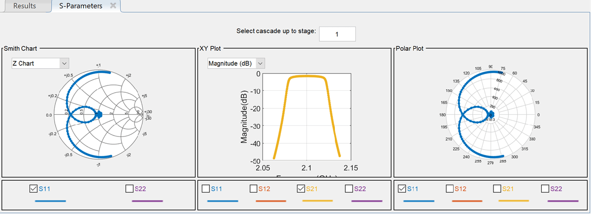
SelectS-Parameters Plotbutton. This allows you to plot Smith® chart, polar plot, magnitude, phase and real, and imaginary parts of S-parameters of the RF System and over stages.
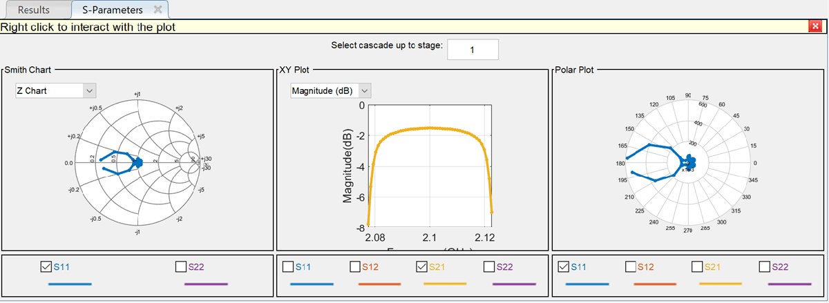
Set thePlot Bandwidthto75andResolutionto250underPlotssection.

The S-parameters data is displayed as follows.
SelectPhase (deg)from the drop-down menu of XY Plot inS-Parameterspane to plot the phase of the S21.

The phase plot is displayed as shown.

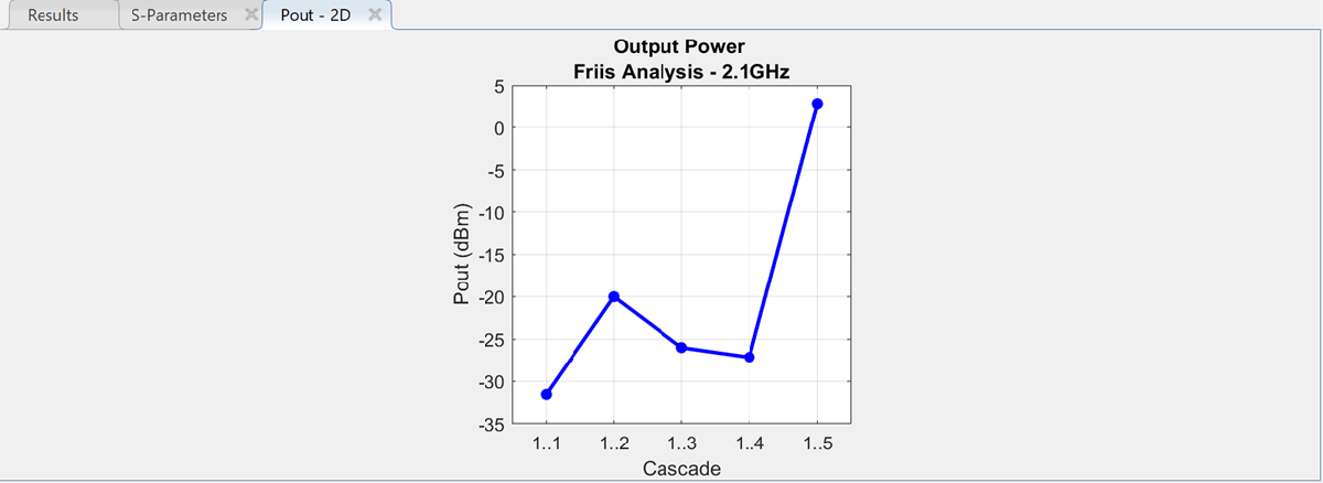
Plot the output power of the RF system using the2D Plotbutton. Select2D Plotbutton and chooseOutput Power - Pout.

2-D output power is displayed.
Plot the transducer gain of the RF system using the2D Plotbutton. Select2D Plotbutton and chooseTransducer Gain - GainT.

Perform HB Analysis on RF Receiver Designed Usingrfsystem
Design an RF receiver using therfsystemsystem object. View the object in the theRF Budget Analyzerapp to perform harmonic balance (HB) analysis.
Create fifth- and seventh-order bandpass RF filters.
f1 = rffilter('ResponseType','Bandpass','FilterOrder',5,...'PassbandFrequency',[4.85 5.15]*1e9); f2 = rffilter('ResponseType','Bandpass','FilterOrder'7...'PassbandFrequency',[10 130]*1e6);
Create two amplifier objects with3dB and5dB gain, respectively.
a1 = amplifier('Gain',3,'NF',1.53,'OIP3',35); a2 = amplifier('Gain',5,'NF',8,'OIP3',37);
Create a modulator with a local frequency of4.93GHz.
d = modulator('Gain',0,'NF',4,'OIP3',50,'LO',4.93e9,...'ConverterType','Down');
Design an RF receiver with the budget elements at an input frequency of5GHz, an available input power of –30dBm, and a bandwidth of10MHz.
rfb = rfbudget([f1 a1 d f2 a2],5e9,-30,10e6);
Create an RF system for the RF receiver using therfbudgetobject.
rfs = rfsystem(rfb);
Open an RF Blockset model of the designed RF system using theopen_systemobject function.
open_system(rfs)

Type rfBudgetAnalyzer(rfs) command at the MATLAB® command line to open this RF system in theRF Budget Analyzerapp.

To conduct HB analysis in the app, click theHB-Analyzebutton.

Related Examples
Programmatic Use
Tips
TheRF Budget Analyzerapp accepts
0Hz asInput Frequencyfor a system. You can set theInput Frequencyin theSystem Parameterssection.TheRF Budget Analyzerapp does not accept
0Hz asLO Frequency. This is applicable to Modulator and Demodulator elements.The output frequencies from theRF Budget Analyzerapp are always positive.
The Filter element allows you to use only the
'Transfer function'implementation when you set theFilter Typeto'InverseChebyshev'in theElement Parameterspane.To design an antenna element using theRF Budget Analyzerapp, in the Antenna Element pane, setAntenna Sourceto
Isotropic radiator.You can also design an antenna element using theAntenna Designerapp or an antenna object. To use theAntenna Designerapp or the antenna object, you need Antenna Toolbox™ license.Antenna elements designed using a default antenna object require larger memory. To speed up the simulation, design your antenna element at a high frequency,
2GHz or more.
References
[1] Pozar, David M.Microwave Engineering. 4th ed. Hoboken, NJ: Wiley, 2012.
版本;n History
You can also select a web site from the following list:
Americas
- América Latina(Español)
- Canada(English)
- United States(English)
Europe
- Belgium(English)
- Denmark(English)
- Deutschland(Deutsch)
- España(Español)
- Finland(English)
- France(Français)
- Ireland(English)
- Italia(Italiano)
- Luxembourg(English)
- Netherlands(English)
- Norway(English)
- Österreich(Deutsch)
- Portugal(English)
- Sweden(English)
- Switzerland
- United Kingdom(English)