Highway Lane Change
This example shows how to perceive surround-view information and use it to design an automated lane change maneuver system for highway driving scenarios.
Introduction
An automated lane change maneuver (LCM) system enables the ego vehicle to automatically move from one lane to another lane. An LCM system models the longitudinal and lateral control dynamics for an automated lane change. LCM systems scan the environment for most important objects (MIOs) using onboard sensors, identify an optimal trajectory that avoids these objects, and steer the ego vehicle along the identified trajectory.
This example shows how to create a test bench model to test the sensor fusion, planner, and controller components of an LCM system. This example uses five vision sensors and one radar sensor to detect other vehicles from the surrounding view of the ego vehicle. It uses a joint probabilistic data association (JPDA) based tracker to track the fused detections from these multiple sensors. The lane change planner then generates a feasible trajectory for the tracks to negotiate a lane change that is executed by the lane change controller. In this example, you:
分区算法和测试台上— The model is partitioned into lane change algorithm models and a test bench model. The algorithm models implement the individual components of the LCM system. The test bench includes the integration of the algorithm models and testing framework.
Explore the test bench model— The test bench model contains the testing framework, which includes the sensors and environment, ego vehicle dynamics model, and metrics assessment using ground truth.
Explore the algorithm models— Algorithm models are reference models that implement the sensor fusion, planner, and controller components to build the lane change application.
Simulate and visualize system behavior— Simulate the test bench model to test the integration of sensor fusion and tracking with planning and controls to perform lane change maneuvers on a curved road with multiple vehicles.
Explore other scenarios— These scenarios test the system under additional conditions.
您可以应用中使用的建模模式example to test your own LCM system.
Partition Algorithm and Test Bench
模式l is partitioned into separate algorithm models and a test bench model.
Algorithm models — Algorithm models are reference models that implement the functionality of individual components.
Test bench model — TheHighway Lane Change Test Benchspecifies the stimulus and environment for testing the algorithm models.
Explore Test Bench Model
In this example, you use a system-level simulation test bench model to explore the behavior of a probabilistic sensor-based LCM system.
To explore the test bench model, open a working copy of the project example files. MATLAB® copies the files to an example folder so you can edit them.
addpath(fullfile(matlabroot,"toolbox","driving","drivingdemos")); helperDrivingProjectSetup("HighwayLaneChange.zip",workDir=pwd);
Open the system-level simulation test bench model.
open_system("HighwayLaneChangeTestBench")
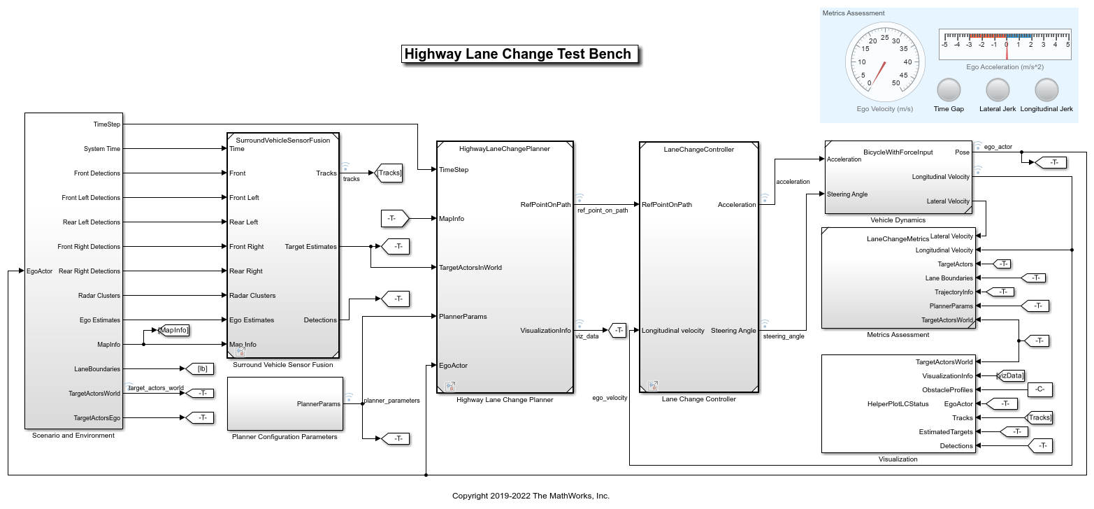
Opening this model runs thehelperSLHighwayLaneChangeSetupfunction, which initializes the road scenario using thedrivingScenarioobject in the base workspace. It also configures the sensor configuration parameters, tracker design parameters, planner configuration parameters, controller design parameters, vehicle model parameters, and the Simulink® bus signals required for defining the inputs and outputs for theHighwayLaneChangeTestBenchmodel.
The test bench model contains these subsystems:
Scenario and Environment— Subsystem that specifies the scene, vehicles, sensors, and map data used for simulation. This example uses five vision sensors, one radar sensor, and an INS sensor.Surround Vehicle Sensor Fusion— Subsystem that fuses the detections from multiple sensors to produce tracks.Planner Configuration Parameters— Subsystem that specifies the configuration parameters required for the planner algorithm.Highway Lane Change Planner— Subsystem that implements the lane change planner algorithm for highway driving.Lane Change Controller— Subsystem that specifies the path-following controller that generates control commands to steer the ego vehicle along the generated trajectory.Vehicle Dynamics— Subsystem that specifies the dynamic model for the ego vehicle.Metrics Assessment— Subsystem that specifies metrics to assess system-level behavior.
TheHighway Lane Change Planner,Lane Change Controller, andMetrics Assessmentsubsystems are the same as those in theHighway Lane Change Planner and Controllerexample. However, whereas the lane change planner in the Highway Lane Change Planner and Controller example, uses ground truth information from the scenario to detect MIOs, the lane change planner in this example uses tracks from surround vehicle sensor fusion to detect the MIOs. TheVehicle Dynamicssubsystem models the ego vehicle using a Bicycle Model block, and updates its state using commands received from theLane Change Controllersubsystem.
TheScenario and Environmentsubsystem uses theScenario Readerblock to provide road network and vehicle ground truth positions. This block also outputs map data required for the highway lane change planner algorithm. This subsystem outputs the detections from the vision sensors, clusters from the radar sensor, and ego-estimated position from the INS sensor required for the sensor fusion and tracking algorithm. Open theScenario and Environmentsubsystem.
open_system("HighwayLaneChangeTestBench/Scenario and Environment")

TheScenario Readerblock configures the driving scenario and outputs actor poses, which control the positions of the target vehicles.
TheVehicle To Worldblock converts actor poses from the coordinates of the ego vehicle to the world coordinates.
TheVision Detection Generatorblock simulates object detections using a camera sensor model.
TheDriving Radar Data Generatorblock simulates object detections based on a statistical model. It also outputs clustered object detections for further processing.
TheINSblock models the measurements from the inertial navigation system and global navigation satellite system and outputs the fused measurements. It outputs the noise-corrupted position, velocity, and orientation of the ego vehicle.
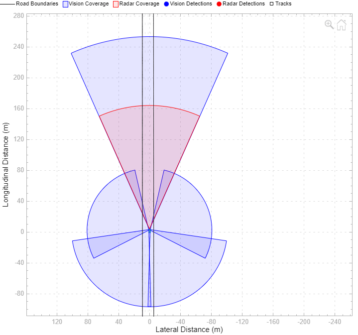
The subsystem configures five vision sensors and a radar sensor to capture the surround view of the vehicle. These sensors are mounted on different locations on the ego vehicle to capture a 360-degree view.
TheBird's-Eye Scopedisplays sensor coverage using a cuboid representation. The radar coverage area and detections are in red. The vision coverage area and detections are in blue.
TheVehicle Dynamicssubsystem uses a Bicycle Model block to model the ego vehicle. For more details on theVehicle Dynamicssubsystem, see theHighway Lane Followingexample. Open theVehicle Dynamicssubsystem.
open_system("HighwayLaneChangeTestBench/Vehicle Dynamics");

The Bicycle Model block implements a rigid two-axle single-track vehicle body model to calculate longitudinal, lateral, and yaw motion. The block accounts for body mass, aerodynamic drag, and weight distribution between the axles due to acceleration and steering. For more details, seeBicycle Model(Automated Driving Toolbox).
TheMetric Assessmentsubsystem enables system-level metric evaluations using the ground truth information from the scenario. Open theMetrics Assessmentsubsystem.
open_system("HighwayLaneChangeTestBench/Metrics Assessment")
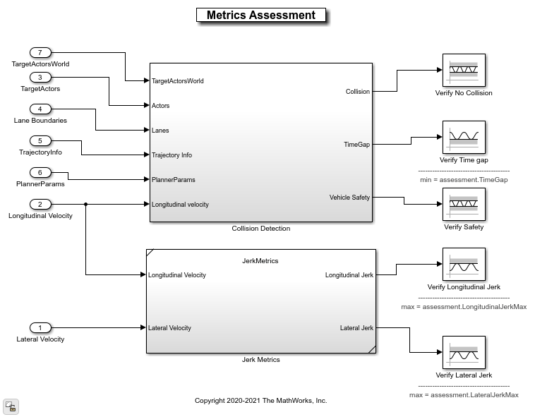
The
Collision Detectionsubsystem detects the collision of the ego vehicle with other vehicles and halts the simulation if it detects a collision. The subsystem also computes theTimeGapparameter using the distance to the lead vehicle (headway) and the longitudinal velocity of the ego vehicle. This parameter is evaluated against prescribed limits.The
Jerk Metricssubsystem computes theLongitudinalJerkandLateralJerkparameters using longitudinal velocity and lateral velocity, respectively. These parameters are evaluated against prescribed limits.
For more details on how to validate the metrics automatically using Simulink Test, see theAutomate Testing for Highway Lane Changeexample.
Explore Algorithm Models
The lane change system is developed by integrating the surround vehicle sensor fusion, lane-change planner, and lane-following controller components.
The surround vehicle sensor fusion algorithm model fuses vehicle detections from cameras and radar sensors and tracks the detected vehicles using the central-level tracking method. Open theSurround Vehicle Sensor Fusion算法米odel.
open_system("SurroundVehicleSensorFusion")

The surround vehicle sensor fusion model takes the vehicle detections from vision sensors and clusters from the radar sensor as inputs.
The
Vision Detection Concatenationblock concatenates the vision detections.The
Delete Velocity From Visionblock is a MATLAB Function block that deletes velocity information from vision detections.The
Vision and Radar Detection Concatenationblock concatenates the vision and radar detections.The
Add Localization Informationblock is a MATLAB Function block that adds localization information for the ego vehicle to the concatenated detections using an estimated ego vehicle pose from the INS sensor. This enables the tracker to track in the global frame, and minimizes the effect on the tracks of lane change maneuvers by the ego vehicle.The
helperJPDATrackerblock performs fusion and manages the tracks of stationary and moving objects. The tracker fuses the information contained in the concatenated detections and tracks the objects around the ego vehicle. It estimates tracks in the Frenet coordinate system. It usesmapInfofrom the scenario to estimate the tracks in Frenet coordinate system. The tracker then outputs a list of confirmed tracks. These tracks are updated at a prediction time driven by a digital clock in theScenario and Environmentsubsystem.
For more details on the algorithm, see theObject Tracking and Motion Planning Using Frenet Reference Pathexample.
The highway lane change planner is a fundamental component of a highway lane change system. This component is expected to handle different driving behaviors to safely navigate the ego vehicle from one point to another point. TheHighway Lane Change Planner算法米odel contains a terminal state sampler, motion planner, and motion prediction module. The terminal state sampler samples terminal states based on the planner parameters and the current state of both the ego vehicle and other vehicles in the scenario. The motion prediction module predicts the future motion of MIOs. The motion planner samples trajectories and outputs an optimal trajectory. Open theHighway Lane Change Planner算法米odel.
open_system("HighwayLaneChangePlanner")

The algorithm model implements the main algorithm for the highway lane change system. The reference model reads map data, actor poses (in world coordinates), and planner parameters from theScenario and Environment子系统进行轨迹规划。模式l uses the Frenet coordinate system to find the MIOs surrounding the ego vehicle. Then, the model samples terminal states for different behaviors, predicts the motion of target actors, and generates multiple trajectories. Finally, the model evaluates the costs of generated trajectories and checks for the possibility of collision and kinematic feasibility to estimate the optimal trajectory. For more details, see theGenerate Code for Highway Lane Change Plannerexample.
TheLane Change Controllerreference model simulates a path-following control mechanism that keeps the ego vehicle traveling along the generated trajectory while tracking a set velocity. Open theLane Change Controllerreference model.
open_system("LaneChangeController");
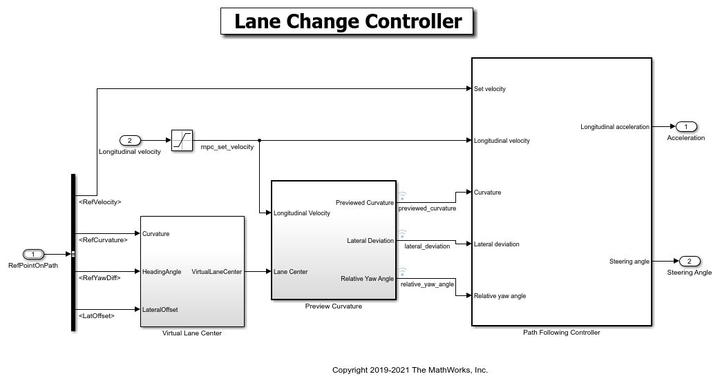
The controller adjusts both the longitudinal acceleration and front steering angle of the ego vehicle to ensure that the ego vehicle travels along the generated trajectory. The controller computes optimal control actions while satisfying velocity, acceleration, and steering angle constraints using adaptive model predictive control (MPC). For more details on the integration of the highway lane change planner and controller, see theHighway Lane Change Planner and Controllerexample.
Simulate and Visualize System Behavior
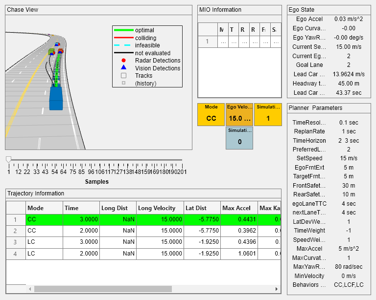
Set up and run theHighwayLaneChangeTestBenchsimulation model to visualize the behavior of the system during a lane change. TheVisualizationblock in the model creates a MATLAB figure that shows the chase view and top view of the scenario and plots the ego vehicle, tracks, sampled trajectories, capsule list, and other vehicles in the scenario.
Disable the MPC update messages.
mpcverbosity("off");
Configure theHighwayLaneChangeTestBenchmodel to use thescenario_LC_15_StopnGo_Curvedscenario.
helperSLHighwayLaneChangeSetup(scenarioFcnName="scenario_LC_15_StopnGo_Curved"); sim("HighwayLaneChangeTestBench");
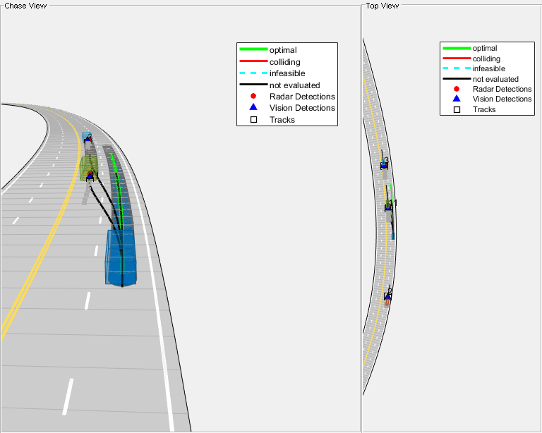
During the simulation, the model logs signals to the base workspace aslogsout. You can analyze the simulation results and debug any failures in the system behavior using theHelperAnalyzeLCSimulationResultsobject. ThevisualizeSimulationDatafunction of the method creates a MATLAB figure and plots a chase view of the scenario along with detections and tracks. For more details on this figure, see theGenerate Code for Highway Lane Change Plannerexample. Run the function and explore the plot.
visualizatonObj = HelperAnalyzeLCSimulationResults(logsout); visualizatonObj.visualizeSimulationData()
Explore Other Scenarios
In this example, you have explored the system behavior for thescenario_LC_15_StopnGo_Curvedscenario, but you can use the same test bench model to explore other scenarios. This is a list of scenarios that are compatible with theHighwayLaneChangeTestBenchmodel.
scenario_LC_01_SlowMoving scenario_LC_02_SlowMovingWithPassingCar scenario_LC_03_DisabledCar scenario_LC_04_CutInWithBrake scenario_LC_05_SingleLaneChange scenario_LC_06_DoubleLaneChange scenario_LC_07_RightLaneChange scenario_LC_08_SlowmovingCar_Curved scenario_LC_09_CutInWithBrake_Curved scenario_LC_10_SingleLaneChange_Curved scenario_LC_11_MergingCar_HighwayEntry scenario_LC_12_CutInCar_HighwayEntry scenario_LC_13_DisabledCar_Ushape scenario_LC_14_DoubleLaneChange_Ushape scenario_LC_15_StopnGo_Curved[Default]
Each of these scenarios have been created using theDriving Scenario Designerand exported to a scenario file. Examine the comments in each file for more details on the road and vehicles in each scenario. You can configure theHighwayLaneChangeTestBenchmodel and workspace to simulate these scenarios using thehelperSLHighwayLaneChangeSetupfunction. For example, you can configure the simulation for a curved road scenario using this command.
helperSLHighwayLaneChangeSetup(scenarioFcnName="scenario_LC_10_SingleLaneChange_Curved");
Conclusion
In this example, you designed and simulated a highway lane change maneuver system using information perceived from surround view. This example showed how to integrate sensor fusion, planner, and controller components to simulate a highway lane change system in a closed-loop environment. The example also demonstrated various evaluation metrics to validate the performance of the designed system. If you have a Simulink Coder™ license and Embedded Coder™ license, you can generate ready-to-deploy code of the algorithm models for an embedded real-time target (ERT).
Enable the MPC update messages again.
mpcverbosity("on");
See Also
trajectoryOptimalFrenet(Navigation Toolbox)
Related Topics
You can also select a web site from the following list:
Americas
- América Latina(Español)
- Canada(English)
- United States(English)
Europe
- Belgium(English)
- Denmark(English)
- Deutschland(Deutsch)
- España(Español)
- Finland(English)
- France(Français)
- Ireland(English)
- Italia(Italiano)
- Luxembourg(English)
- Netherlands(English)
- Norway(English)
- Österreich(Deutsch)
- Portugal(English)
- Sweden(English)
- Switzerland
- United Kingdom(English)