Automate Ground Truth Labeling of Lane Boundaries
This example shows how to develop an algorithm for the automated marking of lane boundaries in theGround Truth Labeler应用程序。
The Ground Truth Labeler App
Good ground truth data is crucial for developing driving algorithms and evaluating their performances. However, creating a rich and diverse set of annotated driving data requires significant time and resources. TheGround Truth Labeler应用使得这个过程有效。你可以使用这个app as a fully manual annotation tool to mark lane boundaries, vehicle bounding boxes, and other objects of interest for a vision system. However, manual labeling requires a significant amount of time and resources. This app also provides a framework to create algorithms to extend and automate the labeling process. You can use the algorithms you create to quickly label entire data sets, and then follow it up with a more efficient, shorter manual verification step. You can also edit the results of the automation step to account for challenging scenarios that the automation algorithm might have missed. This example describes how to insert a lane detection algorithm into the automation workflow of the app.
Create a Lane Detection Algorithm
First, create a lane detection algorithm. TheVisual Perception Using Monocular Cameraexample describes the process of detecting lane boundaries, and thehelperMonoSensorclass packages that algorithm into a single, reusable class. Try out the algorithm on a single video frame to detect the left ego lane boundary.
configData = load('birdsEyeConfig'); sensor = configData.birdsEyeConfig.Sensor; monoSensor = helperMonoSensor(sensor); I = imread('road.png'); sensorOut = processFrame(monoSensor, I); lb = sensorOut.leftEgoBoundary; figure IwithLane = insertLaneBoundary(I, lb, sensor, [3 30],'Color','blue'); imshow(IwithLane); title('Detected Left Lane Boundary Model');

Mark Lane Boundary Points
The lane detected in the previous step is amodeland must be converted to a set of discrete points. These points are similar to what a user might manually place on the image. In the camera view, parts of the lane boundary closer to the vehicle (lower part of the camera image) will span more pixels than the further parts. Consequently, a user would place more points with higher confidence in the lower parts of the camera image. To replicate this behavior, determine the lane boundary locations from the boundary model more densely at points closer to the vehicle.
ROI = [3 30]; xPoints = [3 3.5 4 5 7 12 30]';% More dense closer to the vehicleyPoints = lb.computeBoundaryModel(xPoints);% Find corresponding image locations.boundaryPointsOnImage = vehicleToImage(sensor, [xPoints, yPoints]); imshow(I) holdonplot(boundaryPointsOnImage(:,1), boundaryPointsOnImage(:,2),。..'o',。..'MarkerEdgeColor','b',。..'MarkerFaceColor','b',。..'MarkerSize',10) title('Automatically Marked Lane Boundary Points'); holdoff

Integrate Lane Detection Algorithm Into Ground Truth Labeler
To incorporate this lane detection algorithm into the automation workflow of the app, construct a class that inherits from the abstract base classvision.labeler.AutomationAlgorithm。This base class defines properties and signatures for methods that the app uses for configuring and running the custom algorithm. The Ground Truth Labeler app provides a convenient way to obtain an initial automation class template. For details, seeCreate Automation Algorithm for Labeling。TheAutoLaneMarkingclass is based off of this template and provides you with a ready-to-use automation class for lane detection. The comments of the class outline the basic steps needed to implement each API call.
Step 1 contains properties that define the name and description of the algorithm, and the directions for using the algorithm.
%---------------------------------------------------------------------- % Step 1: Define required properties describing the algorithm. This % includes Name, Description, and UserDirections. properties(Constant)
% Name: Give a name for your algorithm. Name = 'Lane Detector';
% Description: Provide a one-line description for your algorithm. Description = 'Automatically detect lane-like features';
% UserDirections: Provide a set of directions that are displayed % when this algorithm is invoked. The directions % are to be provided as a cell array of character % vectors, with each element of the cell array % representing a step in the list of directions. UserDirections = {... 'Load a MonoCamera configuration object from the workspace using the settings panel',... 'Specify additional parameters in the settings panel',... 'Run the algorithm',... 'Manually inspect and modify results if needed'}; end
Step 2 contains the custom properties needed for the core algorithm. The necessary properties were determined from the lane detection and lane point creation section above.
%--------------------------------------------------------------------- % Step 2: Define properties to be used during the algorithm. These are % user-defined properties that can be defined to manage algorithm % execution. properties %MonoCamera % The monoCamera object associated with this video MonoCamera = []; %MonoCameraVarname % The workspace variable name of the monoCamera object MonoCameraVarname = ''; %BirdsEyeConfig % The birdsEyeView object needed to create the bird's-eye view BirdsEyeConfig = []; %MaxNumLanes % The maximum number of lanes the algorithm tries to annotate MaxNumLanes = 2; %ROI % The region of interest around the vehicle used to search for % lanes ROI = [3, 30, -3, 3]; %LaneMaskSensitivity % The sensitivity parameter used in the segmentLaneMarkerRidge function LaneMaskSensitivity = 0.25; %LaneBoundaryWidth % The lane boundary width, used in findParabolicLaneBoundaries LaneBoundaryWidth = 0.6; %XPoints % The x-axis points along which to mark the lane boundaries XPoints = [3 3.5 4 4.5 5 6 7 10 30]; end
Step 3 deals with function definitions. The first function,checkLabelDefinition, ensures that only labels of the appropriate type are enabled for automation. For lane detection, you need to ensure that only labels of typeLineare enabled, so this version of the function checks theTypeof the labels:
function TF = checkLabelDefinition(~, labelDef) % Lane detection only works with Line type labels TF = labelDef.Type == labelType.Line; end
The next function ischeckSetup。Note that this algorithmrequiresamonoCamerasensor configuration to be available. All other properties have defined reasonable defaults.
function TF = checkSetup(algObj, ~) % This is the only required input TF = ~isempty(algObj.MonoCamera); end
Next, thesettingsDialog函数获取和修改专业版perties defined in Step 2. This API call lets you create a dialog box that opens when a user clicks theSettingsbutton in theAutomatetab. To create this dialog box, use theinputdlgfunction to quickly create a simple modal window to ask a user to specify themonoCameraobject. The following snippet of code outlines the basic syntax. The fullAutoLaneMarkingcode extends this logic and also adds input validation steps.
% Describe the inputs prompt = {... 'Enter the MonoCamera variable name',... 'Maximum number of Lanes',... }; defaultAnswer = {... '',... num2str(2),... };
% Create an input dialog name = 'Settings for lane detection'; numLines = 1; options.Resize = 'on'; options.WindowStyle = 'normal'; options.Interpreter = 'none'; answer = inputdlg(prompt,name,numLines,defaultAnswer,options);
% Obtain the inputs monoCameraVarname = answer{1}; maxNumberOfLanes = answer{2};
Step 4 specifies the execution functions. Some automation algorithms need to implement aninitializeroutine to populate the initial algorithm state based on the existing labels in the app. This lane detection algorithm works on each frame independently, so the default version of the template has been trimmed to take no action.
function initialize(~, ~, ~) end
Next, therunfunction defines the core lane detection algorithm of this automation class.rungets called for each video frame, and expects the automation class to return a set of labels. Therunfunction inAutoLaneMarkingcontains the logic introduced previously for the lane detection and conversion to points. Code fromhelperMonoSensorhas also been folded in for a more compact reference.
function autoLabels = run(algObj, I) Ig = im2gray(I); birdsEyeViewImage = transformImage(algObj.BirdsEyeConfig, Ig); birdsEyeViewBW = segmentLaneMarkerRidge(birdsEyeViewImage, ... algObj.BirdsEyeConfig, algObj.LaneBoundaryWidth, ... 'Sensitivity', algObj.LaneMaskSensitivity);
% Obtain lane candidate points in world coordinates [imageX, imageY] = find(birdsEyeViewBW); boundaryPointsxy = imageToVehicle(algObj.BirdsEyeConfig, [imageY, imageX]);
% Fit requested number of boundaries to it lbs = findParabolicLaneBoundaries(... boundaryPointsxy,algObj.LaneBoundaryWidth, ... 'MaxNumBoundaries',algObj.MaxNumLanes); numDetectedLanes = numel(lbs);
% Convert the model to discrete set of points at the specified % x coordinates boundaryPoints = cell(1,numDetectedLanes); xPoints = algObj.XPoints'; for ind = 1:numel(lbs) yPoints = lbs(ind).computeBoundaryModel(xPoints); boundaryPoints{ind} = vehicleToImage(algObj.MonoCamera, [xPoints, yPoints]); end
% Package up the results in a table autoLabels = table(... boundaryPoints',... repmat(labelType.Line, [numDetectedLanes,1]),... repmat(algObj.SelectedLabelDefinitions.Name, [numDetectedLanes,1])); autoLabels.Properties.VariableNames = {'Position','Type','Name'}; end
Finally, theterminatefunction handles any cleanup or tear-down required after the automation is done. This algorithm does not require any cleanup, so the function is empty.
function terminate(~) end
Use the AutoLaneMarking Automation Class in the App
The packaged version of the lane detection algorithm is now ready for use in theAutoLaneMarkingclass. To use this class in the app:
Create the folder structure required under the current folder, and copy the automation class into it.
mkdir('+vision/+labeler'); copyfile(fullfile(matlabroot,'toolbox','driving','drivingdemos','AutoLaneMarking.m'),'+vision/+labeler');
Load the
monoCamerainformation into the workspace.
configData = load('birdsEyeConfig'); sensor = configData.birdsEyeConfig.Sensor;
Open theGround Truth Labeler应用程序。
groundTruthLabeler caltech_cordova1.avi
On the left pane, click theDefine new ROI labelbutton and define the ROI line style shown. Then click OK.

ClickAlgorithm > Select Algorithm > Refresh list。
ClickAlgorithm > Auto Lane Detection。如果您没有看到这个选项,确保the current working folder has a folder called
+vision/+labeler, with a file namedAutoLaneMarking.min it.

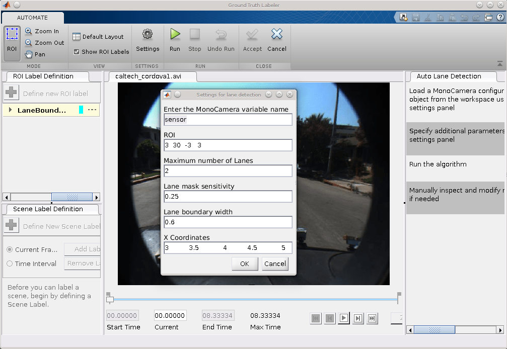
ClickAutomate。A new tab will open, displaying directions for using the algorithm.
ClickSettings, and in the dialog box that opens, enter
sensorin the first text box. Modify other parameters if needed before clickingOK。
ClickRun。The lane detection algorithm progresses on the video. Notice that the results are not satisfactory in some of the frames.
After the run is completed, use the slider or arrow keys to scroll across the video to locate the frames where the algorithm failed.

Manually tweak the results by either moving the lane boundary points or deleting entire boundaries.

Once you are satisfied with the lane boundaries for the entire video, clickAccept。
The auto lane detection part of labeling the video is complete. You can proceed with labeling other objects of interest, save the session, or export the results of this labeling run.
Conclusion
This example showed the steps to incorporate a lane detection algorithm into theGround Truth Labeler应用程序。You can extend this concept to other custom algorithms to simplify and extend the functionality of the app.
See Also
Apps
Objects
Related Topics
You can also select a web site from the following list:
Americas
- América Latina(Español)
- Canada(English)
- United States(English)
Europe
- Belgium(English)
- Denmark(English)
- Deutschland(Deutsch)
- España(Español)
- Finland(English)
- France(Français)
- Ireland(English)
- Italia(Italiano)
- Luxembourg(English)
- Netherlands(English)
- Norway(English)
- Österreich(Deutsch)
- Portugal(English)
- Sweden(English)
- Switzerland
- United Kingdom(English)