Programmable FIR Filter for FPGA
This example shows how to implement a programmable FIR filter for hardware. You can program the filter to a desired response by loading the coefficients into internal registers using the host interface.
In this example, we will implement a bank of filters, each having different responses, on a chip. If all of the filters have a direct-form FIR structure, and the same length, then we can use a host interface to load the coefficients for each response to a register file when needed.
This design adds latency of a few cycles before the input samples can be processed with the loaded coefficients. However, it has the advantage that the same filter hardware can be programmed with new coefficients to obtain a different filter response. This saves chip area, as otherwise each filter would be implemented separately on the chip.
Model Programmable FIR Filter
Consider two FIR filters, one with a lowpass response and the other with a highpass response. The coefficients are specified by using the Model Properties>Callbacks>InitFcn function.

TheProgrammable FIR via Registersblock loads the lowpass coefficients from the主机行为模型, and processes the input chirp samples first. Then the block loads the highpass coefficients and processes the same chirp samples again.

Thecoeffs_registersblock loads the coefficients into internal registers when thewrite_enablesignal is high. The shadow registers are updated from the coefficients registers when thewrite_donesignal is high. The shadow registers enable simultaneous loading and processing of data by the filter entity. The blocks load the second set of coefficients at the same time as processing the last few input samples.
This model is configured to use a fully parallel architecture for the Discrete FIR Filter block. You can also choose serial architectures from theHDL Block Propertiesmenu.
Simulink Simulation Results
To compare the Design Under Test (DUT) with the reference filter, open the Scope and run the example model.

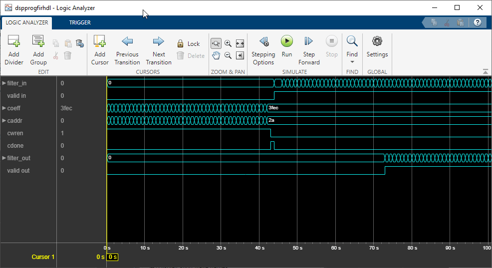
Using the Logic Analyzer
You can also view the signals in the Logic Analyzer. The Logic Analyzer enables you to view multiple signals in one window. It also makes it easy to spot the transitions in the signals.
Launch the Logic Analyzer from the model's toolstrip.

The signals of interest -- input coefficients, write address, write enable, write done, filter in, filter out, reference out, and error have been added to the Logic Analyzer for observation.
The Logic Analyzer display can also be controlled on a per-wave or per-divider basis. To modify an individual wave or divider, select a wave or divider and then click on the "Wave" tab. A useful mode of visualization in the Logic Analyzer is the Analog format.
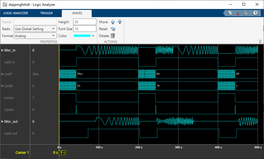
For further information on the Logic Analyzer, refer to theLogic Analyzerdocumentation.
Generate HDL Code and Test Bench
You must have an HDL Coder™ license to generate HDL code for this example model. Use this command to generate HDL code.
systemname = [modelname'/Programmable FIR via Registers']; makehdl(systemname);
Use this command to generate a test bench that compares the results of an HDL simulation against the Simulink simulation behavior. makehdltb(systemname);
ModelSim Simulation Results
The following figure shows the ModelSim® HDL simulator after running the generated .do file scripts for the test bench. Compare the ModelSim result with the Simulink result as plotted before.

You can also select a web site from the following list:
Americas
- 美国拉丁(Español)
- Canada(English)
- United States(English)
Europe
- Belgium(English)
- Denmark(English)
- Deutschland(Deutsch)
- España(Español)
- Finland(English)
- France(Français)
- Ireland(English)
- Italia(Italiano)
- Luxembourg(English)
- Netherlands(English)
- Norway(English)
- Österreich(Deutsch)
- Portugal(English)
- Sweden(English)
- Switzerland
- United Kingdom(English)