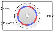
Main Content

Surface Mount PMSM

Three-phase exterior permanent magnet synchronous motor with sinusoidal back electromotive force

  • 库:
  • Powertrain Blockset / Propulsion / Electric Motors and Inverters

    Motor Control Blockset / Electrical Systems / Motors

  • Surface Mount PMSM block

Description

TheSurface Mount PMSMblock implements a three-phase exterior permanent magnet synchronous motor (PMSM) with sinusoidal back electromotive force. The block uses the three-phase input voltages to regulate the individual phase currents, allowing control of the motor torque or speed.

默认情况下, the block sets theSimulation typeparameter toContinuousto use a continuous sample time during simulation. If you want to generate code for fixed-step double- and single-precision targets, considering setting the parameter toDiscrete. Then specify aSample Time, Tsparameter.

On theParameterstab, if you selectBack-emforTorque constant, the block implements one of these equations to calculate the permanent flux linkage constant.

Setting Equation
Back-emf

λ p m = 1 3 K e 1000 P 60 2 π

Torque constant

λ p m = 2 3 K t P

Motor Construction

This figure shows the motor construction with a single pole pair on the motor.

The motor magnetic field due to the permanent magnets creates a sinusoidal rate of change of flux with motor angle.

For the axes convention, thea-phase and permanent magnet fluxes are aligned when motor angleθris zero.

Three-Phase Sinusoidal Model Electrical System

The block implements these equations, expressed in the motor flux reference frame (dq frame). All quantities in the motor reference frame are referred to the stator.

ω e = P ω m d d t i d = 1 L d v d R L d i d + L q L d P ω m i q

d d t i q = 1 L q v q R L q i q L d L q P ω m i d λ p m P ω m L q

T e = 1.5 P [ λ p m i q + ( L d L q ) i d i q ]

TheLqandLdinductances represent the relation between the phase inductance and the motor position due to the saliency of the motor magnets. For the surface mount PMSM, L d = L q .

The equations use these variables.

Lq,Ld

q- and d-axis inductances (H)

R

Resistance of the stator windings (ohm)

iq,id

q- and d-axis currents (A)

vq,vd

q- and d-axis voltages (V)

ωm

Angular mechanical velocity of the motor (rad/s)

ωe

Angular electrical velocity of the motor (rad/s)

λpm

Permanent magnet flux linkage (Wb)

Ke

Back electromotive force (EMF) (Vpk_LL/krpm, where Vpk_LL is the peak voltage line-to-line measurement)

Kt

Torque constant (N·m/A)

P

Number of pole pairs

Te

Electromagnetic torque (Nm)

Θe

Electrical angle (rad)

Mechanical System

The motor angular velocity is given by:

d d t ω m = 1 J ( T e T f F ω m T m ) d θ m d t = ω m

The equations use these variables.

J

Combined inertia of motor and load (kgm^2)

F

Combined viscous friction of motor and load (N·m/(rad/s))

θm

Motor mechanical angular position (rad)

Tm

Motor shaft torque (Nm)

Te

Electromagnetic torque (Nm)

Tf

Motor shaft static friction torque (Nm)

ωm

Angular mechanical velocity of the motor (rad/s)

Power Accounting

For the power accounting, the block implements these equations.

Bus Signal Description Variable Equations

PwrInfo

PwrTrnsfrd— Power transferred between blocks

  • Positive signals indicate flow into block

  • Negative signals indicate flow out of block

PwrMtr

Mechanical power

Pmot

P m o t = ω m T e
PwrBus

Electrical power

Pbus

P b u s = v a n i a + v b n i b + v c n i c

PwrNotTrnsfrd— Power crossing the block boundary, but not transferred

  • Positive signals indicate an input

  • Negative signals indicate a loss

PwrElecLoss

Resistive power loss

Pelec

P e l e c = 3 2 ( R s i s d 2 + R s i s q 2 )
PwrMechLoss

Mechanical power loss

Pmech

WhenPort Configurationis set toTorque:

P m e c h = ( ω m 2 F + | ω m | T f )

WhenPort Configurationis set toSpeed:

P m e c h = 0

PwrStored— Stored energy rate of change

  • Positive signals indicate an increase

  • Negative signals indicate a decrease

PwrMtrStored

Stored motor power

Pstr

P s t r = P b u s + P m o t + P e l e c + P m e c h

The equations use these variables.

Rs

Stator resistance (ohm)

ia,ib,ic

Stator phase a, b, and c current (A)

isq,isd

Stator q- and d-axis currents (A)

van,vbn,vcn

Stator phase a, b, and c voltage (V)

ωm

Angular mechanical velocity of the motor (rad/s)

F

Combined motor and load viscous damping N·m/(rad/s)

Te

Electromagnetic torque (Nm)

Tf

Combined motor and load friction torque (Nm)

Ports

Input

expand all

Load torque on the motor shaft,Tm, in N·m.

Dependencies

To create this port, selectTorquefor thePort Configurationparameter.

Angular velocity of the motor,ωm, in rad/s.

Dependencies

To create this port, selectSpeedfor thePort Configurationparameter.

Stator terminal voltages,Va,Vb, andVc, in V.

Output

expand all

The bus signal contains these block calculations.

Signal Description Variable Units

IaStator

定子相电流一

ia

A

IbStator

Stator phase current B

ib

A

IcStator

Stator phase current C

ic

A

IdSync

Direct axis current

id

A

IqSync

Quadrature axis current

iq

A

VdSync

Direct axis voltage

vd

V

VqSync

Quadrature axis voltage

vq

V

MtrSpd

Angular mechanical velocity of the motor

ωm

rad/s

MtrPos

Motor mechanical angular position

θm

rad

MtrTrq

Electromagnetic torque

Te

N·m

PwrInfo

PwrTrnsfrd

PwrMtr

Mechanical power

Pmot

W
PwrBus

Electrical power

Pbus

W

PwrNotTrnsfrd

PwrElecLoss

Resistive power loss

Pelec

W
PwrMechLoss

Mechanical power loss

Pmech

W

PwrStored

PwrMtrStored

Stored motor power

Pstr

W

Phase a, b, c current,ia,ib, andic, in A.

Motor torque,Tmtr, in N·m.

Dependencies

To create this port, selectSpeedfor theMechanical input configurationparameter.

Angular speed of the motor,ωmtr, in rad/s.

Dependencies

To create this port, selectTorquefor theMechanical input configurationparameter.

Parameters

expand all

块的选择

This table summarizes the port configurations.

Port Configuration Creates Input Port Creates Output Port

Torque

LdTrq

MtrSpd

Speed

Spd

MtrTrq

默认情况下, the block uses a continuous sample time during simulation. If you want to generate code for single-precision targets, considering setting the parameter toDiscrete.

Dependencies

SettingSimulation typetoDiscretecreates theSample Time, Tsparameter.

Integration sample time for discrete simulation, in s.

Dependencies

SettingSimulation typetoDiscretecreates theSample Time, Tsparameter.

Load Parameters

Enter the path to the motor parameter ".m" or ".mat" file that you saved using the Motor Control Blockset™ parameter estimation tool. You can also click theBrowsebutton to navigate and select the ".m" or ".mat" file, and updateFileparameter with the file name and path. For details related to the motor parameter estimation process, seeEstimate PMSM Parameters Using Recommended Hardware.

  • Load from file- Click this button to read the estimated motor parameters from the ".m" or ".mat" file (indicated by theFileparameter) and load them to the motor block.

  • Save to file- Click this button to read the motor parameters from the motor block and save them into a ".m" or ".mat" file (with a file name and location that you specify in theFileparameter).

Note

在你点击Save to filebutton, ensure that the target file name in theFileparameter has either ".m" or ".mat" extension. If you use any other file extension, the block displays an error message.

Parameters

Motor pole pairs,P.

Stator phase resistance per phase,Rs, in ohm.

Stator inductance,Ldq, in H.

Permanent flux linkage constant,λpm, in Wb.

Back electromotive force, EMF,Ke, in peak Vpk_LL/krpm. Vpk_LL is the peak voltage line-to-line measurement.

To calculate the permanent flux linkage constant, the block implements this equation.

λ p m = 1 3 K e 1000 P 60 2 π

Torque constant,Kt, in N·m/A.

To calculate the permanent flux linkage constant, the block implements this equation.

λ p m = 2 3 K t P

Mechanical properties of the motor:

  • Inertia,J, in kg.m^2

  • Viscous damping,F, in N·m/(rad/s)

  • Static friction,Tf, in N·m

Dependencies

To enable this parameter, select theTorqueconfiguration parameter.

Initial Values

Initial q- and d-axis currents,iq, id, in A.

Initial motor angular position,θm0, in rad.

Initial angular velocity of the motor,ωm0, in rad/s.

Dependencies

To enable this parameter, select theTorqueconfiguration parameter.

References

[1] Kundur, P.Power System Stability and Control.New York, NY: McGraw Hill, 1993.

[2] Anderson, P. M.Analysis of Faulted Power Systems.Hoboken, NJ: Wiley-IEEE Press, 1995.

Extended Capabilities

C/C++ Code Generation
Generate C and C++ code using Simulink® Coder™.

版本History

Introduced in R2017a