How to Develop DC-DC Converter Control in Simulink
Learn how to model and simulate a DC-DC converter in Simulink®and Simscape Electrical™. Get a demonstration of SEPIC circuit topology and how to model and simulate a DC-DC converter that powers a strip of LEDs. MathWorks engineers show how to use Simulink and Simscape Electrical to develop, simulate, and implement a controller that maintains desired output voltage in the presence of input voltage variations and load changes to achieve a fast and stable response. See how to use control algorithms to generate embedded code optimized for implementing on a Texas Instruments™ C2000™ microcontroller. Also explore hardware-in-the-loop (HIL) testing of the microcontroller using a Speedgoat®real-time target machine.
Highlights:
- Modeling and simulating passive circuit elements, power semiconductors, and varying power sources and loads
- Simulating the converter in continuous and discontinuous conduction modes
- Determining power losses and efficiency of the converter
- Tuning the controller to meet rise time, overshoot, and settling time
- Generating C code from the controller model for implementation on a Texas Instruments C2000 microcontroller
- Using a Simscape Electrical model deployed to an FPGA implemented in a Speedgoat real-time target machine for HIL testing
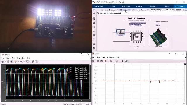
Part 1: Introduction and DemoGet a quick introduction to the topic of DC-DC converter controls, including a customer reference story and demonstration of the entire system working as desired.
Part 2: Converter Modeling and Efficiency ConsiderationsLearn how to model a DC-DC converter in Simscape and use simulation results to generate efficiency maps for the diode and the power switch.
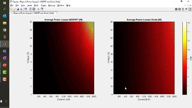
Part 3: Power Losses InvestigationLearn how to use Simscape Electrical functions to generate maps of heat losses to embed in a dedicated model for fast simulations of thermal behavior and sizing of cooling systems.
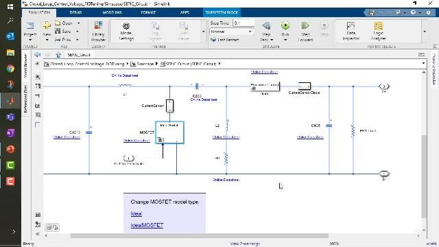
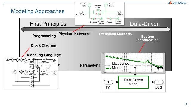
Part 4: Voltage Control DesignLearn how to design and tune a digital PID controller for a DC-DC converter. Using System Identification Toolbox, engineers can simplify the tuning of any power electronics converter without needing to average converter equations.
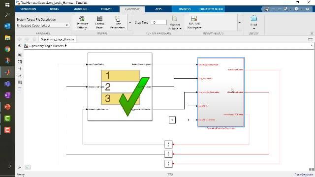
Part 5: Supervisory Logic Design and TestingLearn how to use Stateflow to design supervisory logic state machines that manage your converter desired operating mode.
Part 6: Automatic Code Generation and ConclusionsLearn how to automatically generate C code from your model and use the TI C2000 Hardware Support Package to build, compile and run the application on target hardware.
Related Resources
You can also select a web site from the following list:
Americas
- América Latina(Español)
- Canada(English)
- United States(English)
Europe
- Belgium(English)
- Denmark(English)
- Deutschland(Deutsch)
- España(Español)
- Finland(English)
- France(Français)
- Ireland(English)
- Italia(Italiano)
- Luxembourg(English)
- Netherlands(English)
- Norway(English)
- Österreich(Deutsch)
- Portugal(English)
- Sweden(English)
- Switzerland
- United Kingdom(English)
Asia Pacific
- Australia(English)
- India(English)
- New Zealand(English)
- 中国
- 日本Japanese(日本語)
- 한국Korean(한국어)