5G NR Uplink Vector Waveform Generation
此示例显示了如何使用物理上行链路共享通道(PUSCH)配置和生成5G NR上行链路矢量波形,并通过使用该基础带组件载体来配置和生成音调共享信号(PUSCH)和发声参考信号(SRS)nrwaveformgenerator功能。
Introduction
此示例显示了如何通过使用该示例来参数化和生成5G新广播(NR)上行链路波形nrwaveformgenerator功能。生成的波形包含这些通道和信号。
PUSCH and its associated demodulation reference signal (DM-RS) and phase-tracking reference signal (PT-RS)
SRS
这baseband component carrier waveform in this example is characterized by multiple subcarrier spacing (SCS) carriers and bandwidth parts (BWP), and multiple sequences of PUSCH and SRS transmission instances over the different BWPs. The example also shows how to parameterize and generate uplink control information (UCI) on PUSCH with CG-UCI and SRS for positioning.
For an example on how to generate a 5G uplink waveform with physical uplink control channel (PUCCH), see5G NR上行链路与Pucch矢量波形产生。
波形和载体配置
使用nrulcarrierConfigobject to parameterize the baseband waveform generation. This object contains a set of additional objects associated with the waveform channels and signals and enables you to set these uplink carrier configuration parameters.
此UL载体配置的标签
SCS carrier bandwidth in resource blocks
Carrier cell ID
子帧中生成的波形的长度
窗口
Sample rate of the OFDM-modulated waveform
Carrier frequency for symbol phase compensation
You can control SCS carrier bandwidths and guardbands using theNStartGridandNSizeGrid属性NRSCSCARRIERCONFIGobject.
waveconfig = nrulcarrierConfig;% Create an uplink carrier configuration objectwaveconfig.Label ='UL载体1';% Label for this uplink waveform configurationwaveconfig.ncellid = 0;% Cell identitywaveconfig.ChannelBandWidth = 40;%频道带宽(MHz)waveconfig.frequencyrange ='fr1';% 'FR1' or 'FR2'waveconfig.numsubframes = 10;生成的波形中1 ms子帧的1%数(1、2、4、8插槽每个1 ms子帧,具体取决于SC)waveconfig.windingpercent = 0;相对于FFT长度的窗口百分比百分比waveconfig.SampleRate = [];OFDM调节波形的样本率的%waveconfig.CarrierFrequency = 0;% Carrier frequency in Hz. This property is used for symbol phase% compensation before OFDM modulation%定义一组SCS特异性载体,使用A的最大尺寸% 40 MHz NR channel. See TS 38.101-1 for more information on defined百分比带宽和护栏要求。scscarriers = {nrscscarrierConfig,nrscscarrierConfig};scscarriers {1} .subcarrierspacing = 15;scscarrier {1} .nsizeGrid = 216;ScScarriers {1} .nstartgrid = 0;scscarriers {2} .subcarrierspacing = 30;ScScarrier {2} .nsizeGrid = 106;scscarrier {2} .nstartgrid = 1;
BWPs
A BWP is formed by a set of contiguous resources sharing a numerology on a given SCS carrier. You can define multiple BWPs using a cell array. Each element in the cell array ofnrWavegenBWPConfig对象定义BWP。对于每个BWP,您可以指定SCS,循环前缀(CP)长度和带宽。这SubcarrierSpacingproperty links the BWP to one of the SCS specific carriers defined earlier. TheNStartBWPproperty controls the location of the BWP in the carrier, relative to point A.NStartBWPis expressed in common resource blocks (CRB) in terms of the BWP numerology. Different BWPs can overlap with each other.
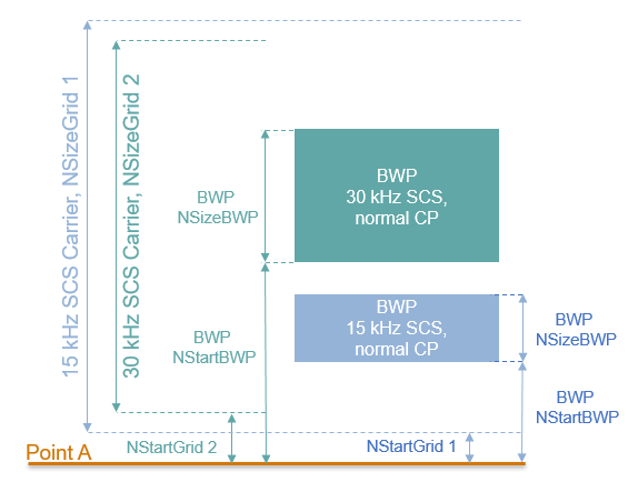
% BWP configurationsbwp = {nrWavegenBWPConfig,nrWavegenBWPConfig}; bwp{1}.BandwidthPartID = 1;% BWP IDBWP {1} .label ='BWP 1 @ 15 kHz';该BWP的%标签BWP {1} .subcarrierspacing = 15;%BWP子载波间距BWP {1} .cyclicprefix ='普通的';% BWP cyclic prefix for 15 kHzbwp {1} .nsizebwp = 25;% Size of BWP in PRBsbwp {1} .nstartbwp = 10;BWP的位置,相对于点A的位置,在CRB中bwp{2}.BandwidthPartID = 2;% BWP IDbwp{2}.Label ='BWP 2 @ 30 kHz';该BWP的%标签BWP {2} .subcarrierspacing = 30;%BWP子载波间距bwp{2}.CyclicPrefix ='普通的';%BWP循环前缀30 kHzbwp{2}.NSizeBWP = 51;% Size of BWP in PRBsbwp{2}.NStartBWP = 40;BWP的位置,相对于点A的位置,在CRB中
PUSCH实例配置
Specify the set of PUSCH transmission instances in the waveform by using a cell array. Each element in the cell array ofnrwavegenpuschconfigobjects defines a sequence of PUSCH transmission instances. This example defines two PUSCH sequences that model two user equipment (UE) transmissions.
General Parameters
为每个Pusch序列设置这些参数。
启用或禁用此Pusch序列。
Specify a label for this PUSCH sequence.
指定携带Pusch的BWP。Pusch使用为此BWP指定的SCS。
Power scaling in dB.
启用或禁用UL-SCH传输通道编码。
rnti。
NID for scrambling the PUSCH bits.
Transform precoding. When transform precoding is
true,,,,the transform precoding is enabled and the resultant waveform is DFT-s-OFDM. When transform precoding is错误的,最终的波形为CP OFDM。Target code rate used to calculate the transport block sizes.
开销参数。
Transmission scheme. When the transmission scheme is
“密码手册”,启用了MIMO预编码,并根据层的数量,天线端口的数量和发送的预编码矩阵指示器选择预编码矩阵。当传输设置为'nonCodebook',使用一个身份矩阵,导致没有MIMO预编码。Symbol modulation.
Number of layers. The number of layers is restricted to a maximum of 4 in uplink as there is only one code word transmission. Nominally, the number of layers is set to 1 when transform precoding is enabled. This value is ignored, when the
DMRS.PortSetproperty is specified.天线端口的数量。启用密码簿传输时使用。天线端口的数量必须大于或等于配置的DM-RS端口数量。
传输预编码矩阵指示器。
冗余版本(RV)序列。
Frequency hopping.
Resource block offset for second hop.
传输块数据源。您可以使用一系列位或以下标准PN序列之一:
'pn9-itu',,,,'pn9',,,,'PN11',,,,'PN15',,,,'PN23'。您可以将发电机的种子指定为形式的单元格数组{'PN9', seed}。If you do not specify a seed, the generator is initialized with all ones.
pusch = {nrwavegenpuschconfig};% Create a PUSCH configuration object for the first UEpusch {1} .enable = 1;%启用Pusch序列pusch{1}。Label ='ue 1- pusch @ 15 khz';此Pusch序列的%标签pusch{1}。BandwidthPartID = 1;% BWP of PUSCH transmissionpusch{1}。Power = 0;DB中的%功率缩放pusch{1}。Coding = 1;%启用UL-SCH运输渠道编码pusch{1}。NID = 1;% Scrambling for data partpusch {1} .rnti = 11;% RNTI for the first UEpusch{1}。TransformPrecoding = false;% Transform precodingpusch {1} .targetCoderate = 0.47;用于计算运输块大小的代码率的%pusch{1}。XOverhead = 0;百分比匹配开销% Transmission settingspusch{1}。TransmissionScheme =“密码手册”;%“密码簿”,“非编码书”pusch {1} .modulation ='QPSK';% 'pi/2-BPSK','QPSK','16QAM','64QAM','256QAM'pusch{1}。NumLayers = 2;Pusch层的%pusch{1}。NumAntennaPorts = 4;% Number of antenna portspusch{1}。TPMI = 0;%传输预编码矩阵指示器(0 ... 27)pusch{1}。RVSequence = [0 2 3 1];% RV sequence to be applied cyclically across the PUSCH allocation sequencepusch {1} .frequencyHopping ='Interslot';%跳跃配置pusch{1}。SecondHopStartPRB = 10;% Resource block offset for second hop% Data sourcepusch{1}。DataSource ='pn9';% Channel data source
Allocation
This figure shows the parameters of the PUSCH allocation.

You can set these parameters to control the PUSCH allocation. These parameters are relative to the BWP.
Pusch映射类型。
Symbols in a slot allocated to each PUSCH instance. For PUSCH mapping type
'A',,,,the start symbol within a slot must be zero and the length can be from 4 to 14 (for normal CP) and up to 12 (for extended CP). For PUSCH mapping type'B',,,,the start symbol can be from any symbol in the slotSlots in a frame used for the sequence of PUSCH.
插槽中分配的时期。空时期表示插槽模式没有重复。
这allocated PRBs relative to the BWP.
pusch{1}。MappingType ='A';%Pusch映射类型('A'(插槽),'B'(非插槽))pusch {1} .symbolAllocation = [0 14];%第一个符号和长度pusch {1} .slotallocation = [0 1];% Allocated slots indices for PUSCH sequencepusch{1}。Period = 5;% Allocation period in slotspusch{1}。PRBSet = 0:10;%PRB分配
PUSCH DM-RS配置
设置DM-RS参数。
%天线端口和DM-RS配置(TS 38.211第6.4.1.1节)pusch {1} .dmrspower = 0;DB中的额外功率增强pusch{1}。DMRS.DMRSConfigurationType = 1;% DM-RS configuration type (1,2)pusch{1}。DMRS.NumCDMGroupsWithoutData = 2;没有数据的DM-RS CDM组数量。该值可以是集合{1,2,3}之一pusch {1} .dmrs.dmrsportset = [0 2];% DM-RS antenna ports used ([] gives port numbers 0:NumLayers-1)pusch {1} .dmrs.dmrstypeaposition = 2;%映射类型A。第一个DM-RS符号位置(2,3)pusch {1} .dmrs.dmrslength = 1;% Number of front-loaded DM-RS symbols (1(single symbol),2(double symbol))pusch{1}。DMRS.DMRSAdditionalPosition = 2;%额外的DM-RS符号位置(最大范围0 ... 3)pusch {1} .dmrs.nidnscid = 1;CP-OFDM的百分比标识(0 ... 65535)。使用空([])使用物理图层单元格身份pusch {1} .dmrs.nscid = 0;CP-OFDM的争夺初始化(0,1)pusch{1}。DMRS.NRSID = 0;% Scrambling identity for DFT-s-OFDM DM-RS (0...1007). Use empty ([]) to use physical layer cell identitypusch {1} .dmrs.grouphopping = true;%组跳配置。仅在启用变换预编码时才使用此属性pusch {1} .dmrs.sequenceHopping = false;% Sequence hopping configuration. This property is used only when transform precoding is enabled
这GroupHoppingproperty is used in DM-RS sequence generation when transform precoding is enabled. You can setGroupHoppingto:
'enable'指示群体跳跃的存在。它由高层参数配置sequenceGroupHopping。'disable'to indicate the presence of sequence hopping. It is configured by higher-layer parameter序列。'neither'to indicate both group hopping and sequence hopping are not present.
没有数据的DM-RS CDM组的数量取决于配置类型。对于DM-RS配置类型1的DM-RS CDM组的最大数量可以为2,对于DM-RS配置类型2,它可以为3。
PUSCH PT-RS配置
设置PT-RS参数。
% PT-RS configuration (TS 38.211 section 6.4.1.2)pusch{1}。EnablePTRS = 0;% Enable or disable the PT-RS (1 or 0)pusch {1} .ptrspower = 0;CP-OFDM的DB中增强PT-RS的额外PT-RS功率pusch {1} .ptrs.timedentess = 1;% Time density (L_PT-RS) of PT-RS (1,2,4)pusch {1} .ptrs.frequencyDentys = 2;% Frequency density (K_PT-RS) of PT-RS for CP-OFDM (2,4)pusch {1} .ptrs.numptrssamples = 2;DFT-S-OFDM的PT-RS样品数量(Ngroupsamp)的%(2,4)pusch{1}。PTRS.NumPTRSGroups = 2;% Number of PT-RS groups (NPTRSGroup) for DFT-s-OFDM (2,4,8)pusch {1} .ptrs.reoffset ='00';% PT-RS resource element offset for CP-OFDM ('00','01','10','11')pusch{1}。PTRS.PTRSPortSet = 0;% PT-RS antenna ports must be a subset of DM-RS ports for CP-OFDMpusch{1}。PTRS.NID = 0;% PT-RS scrambling identity for DFT-s-OFDM (0...1007)
当CP-OFDM启用PT-RS时,DM-RS端口必须在DM-RS配置类型1的0到3范围内,对于DM-RS配置类型2的范围从0到5。DFT-S-OFDM启用了PT-RS,PT-RS组的数量设置为8,必须将PT-RS样本的数量设置为4。
UCI on PUSCH
You can set these parameters to configure the transmission of UCI on PUSCH.
Enable or disable the transmission of HARQ-ACK, CSI part 1, CSI part2, and CG-UCI
HARQ-ACK的数量,CSI第1部分,CSI第2部分和CG-UCI位。
BetaOffsetACK,,,,BetaOffsetCSI1,,,,BetaOffsetCSI2,,,,andBetaOffsetCGUCIcan be set from the tables 9.3-1 and 9.3-2 of TS 38.213.Data source for HARQ-ACK, CSI part 1, CSI part 2, and CG-UCI. You can use an array of bits or one of these standard PN sequences:
'pn9-itu',,,,'pn9',,,,'PN11',,,,'PN15',,,,'PN23'。您可以将发电机的种子指定为形式的单元格数组{'PN9', seed}。If you do not specify a seed, the generator is initialized with all ones.Enable UL-SCH transmission with UCI.
UCIScalingis provided by higher layer parameterscaling,根据TS 38.212,第6.3.2.4节。
pusch {1} .enableAck = true;%启用或禁用harq-ackpusch {1} .numackbits = 5;% Number of HARQ-ACK bitspusch{1}。BetaOffsetACK = 1;% Power factor of HARQ-ACKpusch{1}。DataSourceACK ='pn9';% HARQ-ACK data sourcepusch {1} .enablecsi1 = true;%启用或禁用CSI第1部分pusch {1} .numcsi1bits = 10;CSI第1部分的百分比pusch{1}。BetaOffsetCSI1 = 2;CSI第1部分的功率因数%pusch{1}。DataSourceCSI1 ='pn9';%CSI第1部分数据源pusch {1} .enablecsi2 = true;%启用或禁用CSI第2部分pusch {1} .numcsi2bits = 10;% Number of CSI part 2 bitspusch{1}。BetaOffsetCSI2 = 2;CSI第2部分的功率因数%pusch{1}。DataSourceCSI2 ='pn9';% CSI part 2 data sourcepusch{1}。EnableCGUCI = false;%启用或禁用CG-UCIpusch{1}。NumCGUCIBits = 10;% Number of CG-UCI bitspusch{1}。BetaOffsetCGUCI = 2;CG-UCI的功率因数%pusch{1}。DataSourceCGUCI ='pn9';%CG-UCI数据源pusch{1}。EnableULSCH = true;% Enable or disable UL-SCH when there is UCI transmission on PUSCHpusch {1} .uciscaling = 1;%缩放系数(0.5、0.65、0.8、1)
当启用HARQ-ACK和CG-UCI时,TS 38.212的6.3.2.1.4节将UCI位序列指定为CG-UCI位和HARQ-ACK位的联合。因此,Pusch上的UCI处理将任何活动的CG-UCI源视为HARQ-ACK的扩展,仅为BetaOffsetACK在这种情况下使用。
Specifying Multiple PUSCH Sequences
为第二个BWP指定第二个Pusch序列。
pusch{2} = pusch{1};%创建第二个UE的Pusch配置对象pusch{2}.Enable = 1; pusch{2}.Label ='ue 2 -Pusch @ 30 kHz';pusch {2} .bandwidthpartid = 2;%的Pusch映射到第二个BWPpusch{2}.RNTI = 12;第二个UE的%rntipusch{2}.SymbolAllocation = [0 12]; pusch{2}.SlotAllocation = [5 6 7 8]; pusch{2}.PRBSet = 5:10;%PRB分配,,,,relative to BWPpusch{2}.Period = 10; pusch{2}.TransformPrecoding = 1; pusch{2}.FrequencyHopping ='Interslot';pusch{2}.NumLayers = 1; pusch{2}.RNTI = 1; pusch{2}.DMRS.GroupHopping = false; pusch{2}.DMRS.DMRSPortSet = 1;
SRS实例配置
Specify SRS in the waveform. Each element in the cell array ofnrWavegenSRSConfigobjects defines a sequence of SRS instances associated with a BWP. Define two disabled SRS sequences.
General Parameters
放these parameters for each SRS sequence.
启用或禁用此SRS序列。
Specify a label for this SRS sequence.
指定携带此SRS序列的BWP。SRS序列配置使用该BWP指定的SCS。
Specify the power scaling in dB.
srs = {nrwavegensrsconfig};srs {1} .enable = 0;srs {1} .label ='SRS @ 15 kHz';srs {1} .bandwidthpartid = 1;srs {1} .power = 3;DB中的%功率缩放
SRS Configuration
You can configure these parameters for each SRS sequence.
Number of SRS antenna ports.
Symbols in a slot allocated to each SRS sequence.
Slots within a period used for SRS transmission.
插槽中分配的时期。空时期表示插槽模式没有重复。
SRS序列在RBS中的BWP中的启动位置。
在4-PRB块中的起始位置的额外频率偏移。
Bandwidth and frequency hopping configuration. The occupied bandwidth depends on the properties
CSRS,,,,BSRS,,,,andBhop。放Bhop< BSRSto enable frequency hopping.Transmission comb to specify the SRS frequency density in subcarriers.
Offset of the transmission comb in subcarriers.
Cyclic shift rotating the low-PAPR base sequence. The maximum number of cyclic shifts, 8 or 12, depends on the transmission comb number, 2 or 4. For 4 SRS antenna ports, the subcarrier set allocated to the SRS in the first and third antenna ports depends on the cyclic shift.
插槽内重复的SRS符号的数量。它禁用在
重复符号。放重复= 1for no repetition.小组或序列跳跃。有可能
'neither',,,,'grouphopping'or'sequenceHopping'。Scrambling identity. It initializes the pseudo-random binary sequence when group or sequence hopping are enabled.
srs {1} .numsrsports = 1;% Number of SRS ports (1,2,4)srs{1}.NumSRSSymbols = 4;% Number of SRS symbols in a slot (1,2,4)srs {1} .symbolstart = 10;SRS在插槽中的时间域位置%。(8 ... 13)对于正常CP和(6 ... 11)的扩展CPsrs {1} .slotallocation = 2;% Allocated slots indicessrs {1} .period = 5;% Allocation period in slotssrs{1}.FrequencyStart = 0;% Frequency position of the SRS in BWP in RBssrs{1}.NRRC = 0;%从4个PRB的块(0 ... 67)指定的freqstart的额外偏移量srs {1} .csrs = 13;%带宽配置C_SRS(0 ... 63)。它将分配的带宽控制到SRSsrs{1}.BSRS = 2;% Bandwidth configuration B_SRS (0...3). It controls the allocated bandwidth to the SRSsrs{1}.BHop = 1;%跳跃配置(0...3). Set BHop < BSRS to enable frequency hoppingsrs {1} .ktc = 2;%梳子数(2,4)。它表示每个KTC子载波的SRS分配srs {1} .kbartc = 0;% Subcarrier offset of the SRS sequence (0...KTC-1)srs{1}.CyclicShift = 0;% Cyclic shift number (0...NCSmax-1). NCSmax = 8 for KTC = 2 and NCSmax = 12 for KTC = 4.srs {1} .repeTition = 1;% Repetition factor (1,2,4). It indicates the number of equal consecutive SRS symbols in a slotsrs {1} .groupseqhopping ='neither';%组或序列跳跃(“都不”,“ grouphopping”,“ sequencehopping')srs{1}.NSRSID = 0;% Scrambling identity (0...1023)srs{1}.SRSPositioning = false;%启用用于用户定位的SRS
指定多个SRS序列
Specify the second SRS sequence for the second BWP.
srs{2} = srs{1}; srs{2}.Enable = 0; srs{2}.Label ='SRS @ 30 kHz';srs{2}.BandwidthPartID = 2; srs{2}.NumSRSSymbols = 2; srs{2}.SymbolStart = 12; srs{2}.SlotAllocation = [5 6 7 8]; srs{2}.Period = 10; srs{2}.BSRS = 0; srs{2}.BHop = 0;
Waveform Generation
Assign all the channel and signal parameters to the main carrier configuration objectnrulcarrierConfig,然后生成并绘制波形。
waveconfig.SCSCarriers = scscarriers; waveconfig.BandwidthParts = bwp; waveconfig.PUSCH = pusch; waveconfig.SRS = srs;% Generate complex baseband waveform[waveform,info] = nrWaveformGenerator(waveconfig);
Plot the magnitude of the baseband waveform for the set of antenna ports defined.
数字;情节(ABS(波形));标题(“ 5G上行链路基带波形的大小”);Xlabel('Sample Index');ylabel('震级');

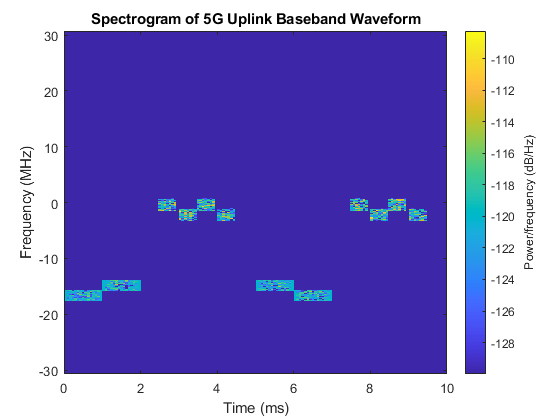
绘制第一个天线端口的波形的光谱。
samplerate = info.ResourceGrids(1).Info.SampleRate; nfft = info.ResourceGrids(1).Info.Nfft; figure; spectrogram(waveform(:,1),ones(nfft,1),0,nfft,'centered',采样率,'yaxis',,,,'MinThreshold',,,,-130); title(“ 5G上行链路基带波形的光谱图”);
波形生成器函数返回时间域波形和结构信息。这信息structure contains the underlying resource element grid and a breakdown of the resources that all the PUSCH and SRS instances use in the waveform.
这ResourceGridsfield is a structure array, which contains these fields.
这resource grid corresponding to each BWP.
包含的资源网格整体带宽ing the channels and signals in each BWP.
An info structure with information corresponding to each BWP. For example, display the information of the first BWP.
disp(“与BWP 1相关的调制信息:”) disp(info.ResourceGrids(1).Info)
Modulation information associated with BWP 1: Nfft: 4096 SampleRate: 61440000 CyclicPrefixLengths: [320 288 288 288 288 288 288 320 288 288 288 ... ] SymbolLengths: [4416 4384 4384 4384 4384 4384 4384 4416 4384 ... ] Windowing: 0 SymbolPhases: [0 0 0 0 0 0 0 0 0 0 0 0 0 0] SymbolsPerSlot: 14 SlotsPerSubframe: 1 SlotsPerFrame: 10 k0: 0
生成的资源网格是3-D矩阵。网格中的不同平面表示天线端口的端口数顺序增加。
也可以看看
功能
对象
Related Topics
You can also select a web site from the following list:
Americas
- América Latina(Español)
- Canada(英语)
- United States(英语)