comm.CarrierSynchronizer
Compensate for carrier frequency offset
Description
Thecomm.CarrierSynchronizerSystem object™ compensates for carrier frequency and phase offsets in signals that use single-carrier modulation schemes. The carrier synchronizer algorithm is compatible with BPSK, QPSK, OQPSK, 8-PSK, PAM, and rectangular QAM modulation schemes.
Note
This System object does not resolve phase ambiguities created by the synchronization algorithm. As indicated in this table, the potential phase ambiguity introduced by the synchronizer depends on the modulation type:
Modulation Phase Ambiguity (degrees) 'BPSK'or'PAM'0, 180 'OQPSK','QPSK', or'QAM'0, 90, 180, 270 '8PSK'0, 45, 90, 135, 180, 225, 270, 315 TheExamplesdemonstrate carrier synchronization and resolution of phase ambiguity.
For best results, apply carrier synchronization to non-oversampled signals, as demonstrated inCorrect Phase and Frequency Offset for 16-QAM Using Coarse and Fine Synchronization。
To compensate for frequency and phase offsets in signals that use single-carrier modulation schemes:
Create the
comm.CarrierSynchronizerobject and set its properties.Call the object, as if it were a function.
To learn more about how System objects work, seeWhat Are System Objects?。
Creation
Description
carrSynch= comm.CarrierSynchronizer
carrSynch= comm.CarrierSynchronizer(Name,Value)
Properties
Usage
Description
Input Arguments
Output Arguments
Object Functions
To use an object function, specify the System object as the first input argument. For example, to release system resources of a System object namedobj, use this syntax:
release(obj)
Examples
Correct Phase and Frequency Offset in QPSK Link
Correct phase and frequency offsets of a QPSK signal passed through an AWGN channel. Using preambles, resolve phase ambiguity.
Define the simulation parameters.
M = 4;% Modulation orderrng(1993)% For repeatable resultsbarker = comm.BarkerCode(。..'Length',13,'SamplesPerFrame',13);% For preamblemsgLen = 1e4; numFrames = 10; frameLen = msgLen/numFrames;
Add preambles to each frame, which are used later when performing phase ambiguity resolution. Generate random data symbols, and apply QPSK modulation.
preamble = (1+barker())/2;% Length 13, unipolardata = zeros(msgLen,1);foridx = 1 : numFrames payload = randi([0 M-1],frameLen-barker.Length,1); data((idx-1)*frameLen + (1:frameLen)) = [preamble; payload];endmodSig = pskmod(data,4,pi/4);
Create acomm.PhaseFrequencyOffsetSystem object™ to introduce phase and frequency offsets to the modulated input signal. Set the phase offset to45degrees, frequency offset to 1 kHz, and sample rate to 10 kHz. The frequency offset is set to 1% of the sample rate.
pfo = comm.PhaseFrequencyOffset(。..'PhaseOffset',45,。..'FrequencyOffset',1e4,。..'SampleRate',1e6);
Create a carrier synchronizer System object to use for correcting the phase and frequency offsets with samples per symbol set to 1.
carrierSync = comm.CarrierSynchronizer(。..'SamplesPerSymbol',1,。..'Modulation','QPSK');
Apply phase and frequency offsets using thepfoSystem object, and then pass the signal through an AWGN channel to add white Gaussian noise.
modSigOffset = pfo(modSig); rxSig = awgn(modSigOffset,12);
Display the scatter plot of the received signal. The data appear in a circle instead of being grouped around the reference constellation points due to the frequency offset.
scatterplot(rxSig)

Use thecarrierSyncSystem object to correct the phase and frequency offset in the received signal.
syncSignal = carrierSync(rxSig);
Use a constellation diagram to display the first and last 1000 symbols of the synchronized signal. Before convergence of the synchronizer loop, the plotted symbols are not grouped around the reference constellation points. After convergence, the plotted symbols are grouped around the reference constellation points.
constDiag = comm.ConstellationDiagram(。..'SymbolsToDisplaySource','Property',。..'SymbolsToDisplay',300,。..'ChannelNames',{'Before convergence','After convergence'},。..'ShowLegend',true,。..'Position',[400 400 400 400]); constDiag([syncSignal(1:1000) syncSignal(9001:10000)]);

Demodulate the synchronized signal. Compute and display the total bit errors and BER.
syncData = pskdemod(syncSignal,4,pi/4); [syncDataTtlErr,syncDataBER] = biterr(。..data(6000:end),syncData(6000:end))
syncDataTtlErr = 8001
syncDataBER = 0.9999
Phase ambiguity in the received signal might cause bit errors. Using the preamble, determine phase ambiguity. Remove this phase ambiguity from the synchronized signal to reduce bit errors.
idx = 9000 + (1:barker.Length); phOffset = angle(modSig(idx) .* conj(syncSignal(idx))); phOffset = round((2/pi) * phOffset);% -1, 0, 1, +/-2phOffset(phOffset==-2) = 2;% Prep for mean operationphOffset = mean((pi/2) * phOffset);% -pi/2, 0, pi/2, or pidisp(['Estimated mean phase offset = ',。..num2str(phOffset*180/pi),' degrees'])
Estimated mean phase offset = 180 degrees
resPhzSig = exp(1i*phOffset) * syncSignal;
Demodulate the signal after resolving the phase ambiguity. Recompute and display the updated total bit errors and BER. Removing the phase ambiguity reduces the BER dramatically.
resPhzData = pskdemod(resPhzSig,4,pi/4); [resPhzTtlErr, resPhzBER] = biterr(。..data(6000:end),resPhzData(6000:end))
resPhzTtlErr= 1
resPhzBER = 1.2497e-04
Estimate Frequency Offset in an 8-PSK Link
Estimate the frequency offset introduced into a noisy 8-PSK signal using a carrier synchronizer System object™.
Define the simulation parameters.
M = 8;% Modulation orderfs = 1e6;% Sample rate (Hz)foffset = 1000;% Frequency offset (Hz)phaseoffset = 15;% Phase offset (deg)snrdb = 20;% Signal-to-noise ratio (dB)
Create acomm.PhaseFrequencyOffsetSystem object to introduce phase and frequency offsets to a modulated signal.
pfo = comm.PhaseFrequencyOffset('PhaseOffset',phaseoffset,。..'FrequencyOffset',foffset,'SampleRate',fs);
Create a carrier synchronizer System object to use for correcting the phase and frequency offsets. Set theModulationproperty to8PSK。
carrierSync = comm.CarrierSynchronizer('Modulation','8PSK');
Generate random data and apply 8-PSK modulation.
data = randi([0 M-1],5000,1); modSig = pskmod(data,M,pi/M);
Apply phase and frequency offsets using the pfo System object, and pass the signal through an AWGN channel to add Gaussian white noise.
modSigOffset = pfo(modSig); rxSig = awgn(modSigOffset,snrdb);
Use the carrier synchronizer to estimate the phase offset of the received signal.
[~,phError] = carrierSync(rxSig);
Determine the frequency offset by using thedifffunction to compute an approximate derivative of the phase error. The derivative must be scaled by
because the phase error is measured in radians.
estFreqOffset = diff(phError)*fs/(2*pi);
Plot the running mean of the estimated frequency offset. After the synchronizer converges to a solution, the mean value of the estimate is approximately equal to the input frequency offset value of 1000 Hz.
rmean = cumsum(estFreqOffset)./(1:length(estFreqOffset))'; plot(rmean) xlabel('Symbols') ylabel(“估计频率偏移(Hz)”) grid

Correct Phase and Frequency Offset for 16-QAM Using Coarse and Fine Synchronization
Compensation of significant phase and frequency offsets for a 16-QAM signal in an AWGN channel is accomplished in two steps. First, correct the coarse frequency offset using the estimate provided by the coarse frequency compensator, and then fine-tune the correction using carrier synchronization. Because of the coarse frequency correction, the carrier synchronizer converges quickly even though the normalized bandwidth is set to a low value. Lower normalized bandwidth values enable better correction for small residual carrier offsets. After applying phase and frequency offset corrections to the received signal, resolve phase ambiguity using the preambles.
Define the simulation parameters.
fs = 10000;% Sample rate (Hz)sps = 4;% Samples per symbolM = 16;% Modulation orderk = log2(M);% Bits per symbolrng(1996)% Set seed for repeatable resultsbarker = comm.BarkerCode(。..% For preamble'Length',13,'SamplesPerFrame',13); msgLen = 1e4; numFrames = 10; frameLen = msgLen/numFrames;
Generate data payloads and add the preamble to each frame. The preamble is later used for phase ambiguity resolution.
preamble = (1+barker())/2;% Length 13, unipolardata = zeros(msgLen, 1);foridx = 1 : numFrames payload = randi([0 M-1],frameLen-barker.Length,1); data((idx-1)*frameLen + (1:frameLen)) = [preamble; payload];end
Create a System object™ for the transmit pulse shape filtering, the receive pulse shape filtering, the QAM coarse frequency compensation, the carrier synchronization, and a constellation diagram.
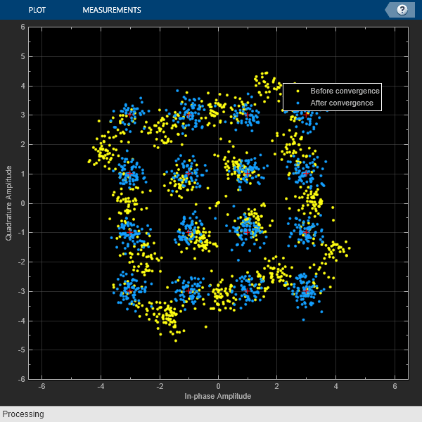
txFilter = comm.RaisedCosineTransmitFilter(。..'OutputSamplesPerSymbol',sps); rxFilter = comm.RaisedCosineReceiveFilter(。..'InputSamplesPerSymbol',sps,。..'DecimationFactor',sps); coarse = comm.CoarseFrequencyCompensator(。..'SampleRate',fs,。..'FrequencyResolution',10); fine = comm.CarrierSynchronizer(。..'DampingFactor',0.4,。..'NormalizedLoopBandwidth',0.001,。..'SamplesPerSymbol',1,。..'Modulation','QAM'); axislimits = [-6 6]; constDiagram = comm.ConstellationDiagram(。..'ReferenceConstellation',qammod(0:M-1,M),。..'ChannelNames',{'Before convergence','After convergence'},。..'ShowLegend',true,。..'XLimits',axislimits,。..'YLimits',axislimits);
Also create a System object for the AWGN channel, and the phase and frequency offset to add impairments to the signal. A phase offset greater than 90 degrees is added to induce a phase ambiguity that results in a constellation quadrant shift.
ebn0 = 8; freqoffset = 110; phaseoffset = 110; awgnChannel = comm.AWGNChannel(。..'EbNo',ebn0,。..'BitsPerSymbol',k,。..'SamplesPerSymbol',sps); pfo = comm.PhaseFrequencyOffset(。..'FrequencyOffset',freqoffset,。..'PhaseOffset',phaseoffset,。..'SampleRate',fs);
Generate random data symbols, apply 16-QAM modulation, and pass the modulated signal through the transmit pulse shaping filter.
txMod = qammod(data,M); txSig = txFilter(txMod);
Apply phase and frequency offsets using thepfoSystem object, and then pass the signal through an AWGN channel to add white Gaussian noise.
txSigOffset = pfo(txSig); rxSig = awgnChannel(txSigOffset);
The coarse frequency compensator System object provides a rough correction for the frequency offset. For the conditions in this example, correcting the frequency offset of the received signal correction to within 10 Hz of the transmitted signal is sufficient.
syncCoarse = coarse(rxSig);
Pass the signal through the receive pulse shaping filter, and apply fine frequency correction.
rxFiltSig = fine(rxFilter(syncCoarse));
Display the constellation diagram of the first and last 1000 symbols in the signal. Before convergence of the synchronization loop, the spiral nature of the diagram indicates that the frequency offset is not corrected. After the carrier synchronizer has converged to a solution, the symbols are aligned with the reference constellation.
constDiagram([rxFiltSig(1:1000) rxFiltSig(9001:end)])
Demodulate the signal. Account for the signal delay caused by the transmit and receive filters to align the received data with the transmitted data. Compute and display the total bit errors and BER. When checking the bit errors, use the later portion of the received signal to be sure the synchronization loop has converged.
rxData = qamdemod(rxFiltSig,M); delay = (txFilter.FilterSpanInSymbols +。..rxFilter.FilterSpanInSymbols) / 2; idxSync = 2000;% Check BER after synchronization loop has converged[syncDataTtlErr,syncDataBER] = biterr(。..data(idxSync:end-delay),rxData(idxSync+delay:end))
syncDataTtlErr = 16116
syncDataBER = 0.5042
Depending on the random data used, there may be bit errors resulting from phase ambiguity in the received signal after the synchronization loop converges and locks. In this case, you can use the preamble to determine and then remove the phase ambiguity from the synchronized signal to reduce bit errors. If phase ambiguity is minimal, the number of bit errors may be unchanged.
idx = 9000 + (1:barker.Length); phOffset = angle(txMod(idx) .* conj(rxFiltSig(idx+delay))); phOffsetEst = mean(phOffset); disp(['Phase offset = ',num2str(rad2deg(phOffsetEst)),' degrees'])
Phase offset = -90.1401 degrees
我* phOffsetEst resPhzSig = exp (1) * rxFiltSig;
Demodulate the signal after resolving the phase ambiguity. Recompute the total bit errors and BER.
resPhzData = qamdemod(resPhzSig,M); [resPhzTtlErr,resPhzBER] = biterr(。..data(idxSync:end-delay),resPhzData(idxSync+delay:end))
resPhzTtlErr= 5
resPhzBER = 1.5643e-04
MSK Signal Recovery
Model channel impairments such as timing phase offset, carrier frequency offset, and carrier phase offset for a minimum shift keying (MSK) signal. Usecomm.MSKTimingSynchronizerandcomm.CarrierSynchronizerSystem objects to synchronize such signals at the receiver. The MSK timing synchronizer recovers the timing offset, while a carrier synchronizer recovers the carrier frequency and phase offsets.
Initialize system variables by running the MATLAB® scriptconfigureMSKSignalRecoveryEx。Define the logical control variablerecoverTimingPhaseto enable timing phase recovery, andrecoverCarrierto enable carrier frequency and phase recovery.
configureMSKSignalRecoveryEx; recoverTimingPhase = true; recoverCarrier = true;
Modeling Channel Impairments
Specify the sample delay,timingOffset, that the channel model applies. Create a variable fractional delay object to introduce the timing delay to the transmitted signal.
timingOffset = 0.2; varDelay = dsp.VariableFractionalDelay;
Create acomm.PhaseFrequencyOffsetSystem object™ to introduce carrier phase and frequency offsets to a modulated signal. Because the MSK modulator upsamples the transmitted symbols, set theSampleRateproperty to the ratio of thesamplesPerSymboland the sample time,Ts。
freqOffset = 50; phaseOffset = 30; pfo = comm.PhaseFrequencyOffset(。..'FrequencyOffset',freqOffset,。..'PhaseOffset',phaseOffset,。..'SampleRate', samplesPerSymbol / Ts);
Set the simulated SNR to 20 dB. Since the MSK modulator generates symbols with 1 Watt of power, the signal power is 1 W or 0 dB W, which is the default value for theawgnchannel signal power input.
SNR = 20;
Timing Phase, Carrier Frequency, and Carrier Phase Synchronization
Create an MSK timing synchronizer to recover symbol timing phase using a fourth-order nonlinearity method.
timeSync = comm.MSKTimingSynchronizer(。..'SamplesPerSymbol',samplesPerSymbol,。..'ErrorUpdateGain',0.02);
Create a carrier synchronizer to recover both carrier frequency and phase. Because the MSK constellation is QPSK with a 0-degree phase offset, set thecomm.CarrierSynchronizeraccordingly.
phaseSync = comm.CarrierSynchronizer(。..'Modulation','QPSK',。..'ModulationPhaseOffset','Custom',。..'CustomPhaseOffset',0,。..'SamplesPerSymbol',1);
Stream Processing Loop
The simulation modulates data using MSK modulation. The modulated symbols pass through the channel model, which applies timing delay, carrier frequency and phase shift, and additive white Gaussian noise. The receiver performs timing phase and carrier frequency and phase recovery. Finally, the signal symbols are demodulated and the bit error rate is calculated. TheplotResultsMSKSignalRecoveryExscript generates scatter plots in this order to show these effects:
Channel impairments
Timing synchronization
Carrier synchronization
At the end of the simulation, the example displays the timing phase, frequency, and phase estimates as a function of simulation time.
forp = 1:numFrames%------------------------------------------------------% Generate and modulate data%------------------------------------------------------txBits = randi([0 1],samplesPerFrame,1); txSym = modem(txBits);%------------------------------------------------------% Transmit through channel%------------------------------------------------------%% Add timing offsetrxSigTimingOff = varDelay(txSym,timingOffset*samplesPerSymbol);%% Add carrier frequency and phase offsetrxSigCFO = pfo(rxSigTimingOff);%% Pass the signal through an AWGN channelrxSig = awgn(rxSigCFO,SNR);%% Save the transmitted signal for plottingplot_rx = rxSig;%%------------------------------------------------------% Timing recovery%------------------------------------------------------ifrecoverTimingPhase% Recover symbol timing phase using% fourth-order nonlinearity method[rxSym,timEst] = timeSync(rxSig);% Calculate the timing delay estimate for each sampletimEst = timEst(1)/samplesPerSymbol;else% Do not apply timing recovery and% simply downsample the received signalrxSym = downsample(rxSig,samplesPerSymbol); timEst = 0;end% Save the timing synchronized received signal for plottingplot_rxTimeSync = rxSym;%------------------------------------------------------% Carrier frequency and phase recovery%------------------------------------------------------ifrecoverCarrier% The following script applies carrier frequency and使用二阶锁相%复苏阶段% loop (PLL), and removes phase ambiguity[rxSym,phEst] = phaseSync(rxSym); removePhaseAmbiguityMSKSignalRecoveryEx; freqShiftEst = mean(diff(phEst)/(Ts*2*pi)); phEst = mod(mean(phEst),360);% in degreeselsefreqShiftEst = 0; phEst = 0;end% Save the phase synchronized received signal for plottingplot_rxPhSync = rxSym;%------------------------------------------------------% Demodulate the received symbols%------------------------------------------------------rxBits = demod(rxSym);%------------------------------------------------------% Calculate the bit error rate%------------------------------------------------------errorStats = BERCalc(txBits,rxBits);%------------------------------------------------------% Plot results%------------------------------------------------------plotResultsMSKSignalRecoveryEx;end


Display the bit error rate and the total number of symbols processed by the error rate calculator.
BitErrorRate = errorStats(1)
BitErrorRate = 4.0001e-06
TotalNumberOfSymbols = errorStats(3)
TotalNumberOfSymbols = 499982
Conclusion and Further Experimentation
The recovery algorithms are demonstrated by using constellation plots taken after timing, carrier frequency, and carrier phase synchronization.
打开脚本创建一个可写的复制example and its supporting files. Then, to show the effects of the recovery algorithms, you can enable and disable the logical control variablesrecoverTimingPhaseandrecoverCarrierand rerun the simulation.
Appendix
This example uses these scripts:
configureMSKSignalRecoveryExplotResultsMSKSignalRecoveryExremovePhaseAmbiguityMSKSignalRecoveryEx
Algorithms
Thecomm.CarrierSynchronizerSystem object is a closed-loop compensator that uses the PLL-based algorithm described in[1]。同步器的输出,yn, is a frequency-shifted version of the complex input signal,xn, for the nth sample. The synchronizer output is
whereλnis the output of the direct digital synthesizer (DDS). The DDS is the discrete-time version of a voltage-controlled oscillator and is a core component of discrete-time phase locked loops. In the context of this System object, the DDS works as an integration filter.

To correct for the frequency offset, first the algorithm determines the phase error,en。The value of the phase error depends on the modulation scheme.
| Modulation | Phase Error |
|---|---|
| QAM or QPSK |
For a detailed description of this equation, see[1]。 |
| BPSK or PAM |
For a detailed description of this equation, see[1]。 |
| 8-PSK |
For a detailed description of this equation, see[2]。 |
| OQPSK |
|
To ensure system stability, the phase error passes through a biquadratic loop filter governed by
whereψnis the output of the loop filter at sample n, andgIis the integrator gain. The integrator gain is determined from the equation
whereθ,d,K0, andKpare determined from the System object properties. Specifically,
whereBnis the normalized loop bandwidth, andζis the damping factor. The phase recovery gain,K0, is equal to the number of samples per symbol. The modulation type determines the phase error detector gain,Kp。
| Modulation | Kp |
|---|---|
| BPSK, PAM, QAM, QPSK, or OQPSK | 2 |
| 8-PSK | 1 |
The output of the loop filter is then passed to the DDS. The DDS is another biquadratic loop filter whose expression is based on the forward Euler integration rule
wheregPis the proportional gain that is expressed as
Theinfoobject function of this System object returns estimates of the normalized pull-in range, the maximum frequency lock delay, and the maximum phase lock delay. The normalized pull-in range,(Δf)pull-in, is expressed in radians and estimated as
The expression for(Δf)pull-inbecomes less accurate as approaches 1.
The maximum frequency lock delay,TFL, and phase lock delay,TPL, are expressed in samples and estimated as
References
[1] Rice, M.Digital Communications: A Discrete-Time Approach。Upper Saddle River, NJ: Prentice Hall, 2009, pp. 359–393.
[2] Zhijie, H., Y. Zhiqiang, Z. Ming, and W. Kuang. “8PSK Demodulation for New Generation DVB-S2.”2004 International Conference on Communications, Circuits and Systems.Vol. 2, 2004, pp. 1447–1450.
Extended Capabilities
Version History
See Also
Objects
Blocks
You can also select a web site from the following list:
Americas
- 美国拉丁(Español)
- Canada(English)
- United States(English)
Europe
- Belgium(English)
- Denmark(English)
- Deutschland(Deutsch)
- España(Español)
- Finland(English)
- France(Français)
- Ireland(English)
- Italia(Italiano)
- Luxembourg(English)
- Netherlands(English)
- Norway(English)
- Österreich(Deutsch)
- Portugal(English)
- Sweden(English)
- Switzerland
- United Kingdom(English)