使用射线跟踪的室内MIMO-OFDM通信链接
此示例显示了如何在室内环境中执行射线跟踪,并使用结果使用MIMO-OFDM技术构建链接级别仿真的通道模型。
Introduction
射线追踪[1]has become a popular technique for radio frequency (RF) analysis, site planning, channel modelling, and link level analysis due to the trend for modern communications systems to operate at RF frequencies in the tens of GHz range. Unlike stochastic models, the ray tracing method is 3-D environment and transceiver sites specific and can have high sensitivity in the surrounding environment. Without a simple formula to calculate distance-based path losses, the ray tracing method relies on numeric simulations, and is typically less costly than field measurements. Results from ray tracing can be used to build multipath channel models for communication systems. For example, a ray tracing based channel model has been specified in Section 8 of TR 38.901[2]用于5G和IEEE 802.11AY for WLAN[3]。
This example starts with ray tracing analysis between one transmitter site and one receiver site in a 3-D conference room. Computed rays are used to construct a deterministic channel model which is specific for the two sites. The channel model is used in the simulation of a MIMO-OFDM communication link. This diagram characterizes the communication link.

这ray tracing is performed in an indoor environment. The same ray tracing methods can be applied to build channel models for indoor or outdoor environments. For ray tracing analysis in an outdoor urban setting, refer to the使用射线跟踪的城市链接和覆盖范围分析例子。
3-D Indoor Scenario
为带有一张桌子和四把椅子的小型会议室以STL格式指定室内3-D地图。STL格式是最常见的3-D MAP格式之一,通常可以从各种3-D软件中的其他3-D MAP格式转换。
mapFileName ="conferenceroom.stl";
定义5.8 GHz的载体频率并计算波长
FC = 5.8E9;lambda = physconst(“ Lightspeed”)/fc;
这transmit antenna is a 4-element uniform linear array (ULA) which has twice of the wavelength between the elements. The receive antenna is a 4x4 uniform rectangular array (URA) which has one wavelength between the elements. Both antennas are specified by anArrayConfigobject.
txarray = arrayconfig("Size",[4 1],'ElementSpacing',2*lambda);rxArray = arrayconfig("Size",,,,[4 4],'ElementSpacing',lambda);
使用HelperviewArray可视化对输入/输出流的天线元件编号的ULA和URA几何形状的功能。
HelperviewArray(TxArray);

HelperviewArray(RxArray);

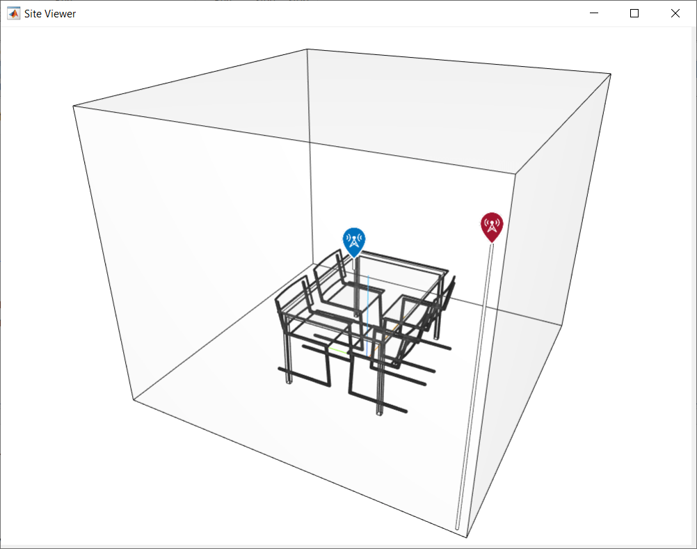
指定一个发射机网站接近上玉米er of the room, which can be a Wi-Fi access point. Specify a receiver site slightly above the table and in front of a chair to represent a laptop or mobile device.
tx = txsite(“笛卡尔”,,,,...“天线”,,,,txArray,...“触角”,[-1.46;-1.42;2.1],...“发射器”,,,,5.8e9); rx = rxsite(“笛卡尔”,,,,...“天线”,rxarray,...“触角”,[。3;.3;.85],...“天线”,,,,[0;90]);
使用SiteViewer使用指定的地图文件函数,以查看站点查看器中3-D中的场景。使用节目功能可视化发射器和接收器。
SiteViewer(“ scenemodel”,mapfileName);显示(TX,'ShowAntennaHeight', 错误的)节目(rx,'ShowAntennaHeight', 错误的)
通过左键单击,通过右键单击或使用滚轮缩放,并通过单击中间按钮并拖动或按CTRL并按下左键并拖动拖动来旋转可视化。

射线追踪
Perform ray tracing analysis between the transmitter and receiver sites and return thecomm.Rayobjects, using the shooting and bouncing rays (SBR) method. Specify the surface material of the scene as wood and search for rays with up to 2 reflections. The SBR method supports up to 10 order of reflections.
pm = paspagationModel(“射线跟踪”,,,,...“坐标系”,,,,“笛卡尔”,,,,...“方法”,,,,"sbr",,,,..."AngularSeparation",,,,“低的”,,,,...“ maxnumeflections”,2,...“表面人物”,,,,“木头”);射线= RayTrace(TX,RX,PM);
Extract the computed rays from the cell array return.
射线=射线{1,1};
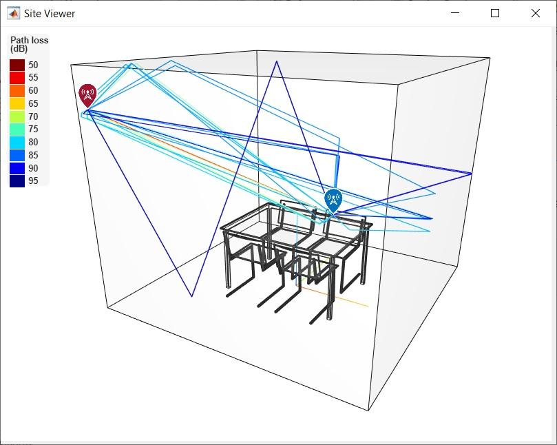
通过查看每个射线的反射次数,传播距离和路径损耗值来检查射线追踪结果。发现了25条射线(一条视线线,6射线带有一根反射,有18射线,带有两种反射)。
[射线。
ans =1×250 1 1 1 1 1 1 2 2 2 2 2 2 2 2 2 2 2 2 2 2 2 2 2 2
[Rays.PropagationDistance]
ans =1×252.7602 2.8118 2.8487 2.8626 3.2029 4.6513 4.6719 2.8988 2.9125 2.9481 3.2475 3.2916 3.3243 4.6821 4.7247 4.7331 4.7433 4.7936 4.9269 4.9464 5.9868 5.9868 6.7170 8.0161 8.0460
[rays.pathloss]
ans =1×2556.5350 72.1633 70.0647 72.3180 73.3102 76.4133 76.4508 81.5418 83.8254 81.5531 83.6891 83.7784 85.7801 85.8271 83.7662 86.0508 91.6822 91.7764 86.5438 86.5283 91.2898 91.2969 94.8444 96.4455 96.4796
使用阴谋功能可在站点查看器中的3-D场景中绘制光线。每个射线根据其路径损耗值进行着色。单击射线以查看有关该射线的信息。
情节(射线,'colormap',喷射,“颜色限制”,[50,95])
射线跟踪中的确定通道模型
使用上述射线跟踪结果创建确定性的多径通道模型。指定接收器的瞬时速度,以反映室内环境中设备的典型低迁移率。
rtchan = Comm.RayTracingChannel(Rays,TX,RX);rtchan.samplerate = 300E6;rtchan.receivervirtualvelocity = [0.1;0.1;0]
rtchan = comm。带有属性的rareTracingChannel:采样:300000000传播仪:[1×25 comm.Ray.ray] minimizizepropagationdelay:true transmitarray:[1×1 arrayConconfig] transmitMitMitMitMitarayOrientientAxes:[3×3 double]接收词:[3×1 double]归一化Impulsersersesses:true normalizechanneloutputs:true channelfiltering:true
使用展示对象函数可视化通道中光线的电源延迟轮廓(PDP),出发角度(AOD)和到达角度(AOA)。在可视化中,除了每个射线的路径损耗外,PDP还考虑了发射阵列模式的增长。
ShowProfile(RTCHAN);

使用信息对象函数以获取传输和接收元素的数量。
rtchaninfo = info(rtchan)
rtchaninfo =带有字段的结构:CarrierFrequency: 5.8000e+09 CoordinateSystem: 'Cartesian' TransmitArrayLocation: [3×1 double] ReceiveArrayLocation: [3×1 double] NumTransmitElements: 4 NumReceiveElements: 16 ChannelFilterDelay: 7 ChannelFilterCoefficients: [25×21 double] NumSamplesProcessed: 0 LastFrameTime: 0
numtx = rtchaninfo.numtransmitelement;numrx = rtchaninfo.numreceiveElements;
系统参数
Configure a communications link that uses LDPC coding, 64-QAM and OFDM with 256 subcarriers. Specify 4 LDPC codewords per frame, which results in 50 OFDM symbols per frame.
%创建LDPC编码器和解码器配置对象cfgldpcenc = ldpcencoderconfig(dvbs2ldpc(1/2));cfgldpcdec = ldpcdecoderconfig(cfgldpcenc);numCodeDeWordSperFrame = 4;codeWordlen = cfgldpcenc.blocklength;每个子载波调制QAM调制的%参数Bitspercarrier = 6;modorder = 2^bitspercarrier;coderate = cfgldpcenc.coperate;%创建OFDM调制器和解调器对象fftlen = 256;cplen = fftlen/4;numguardbandcarriers = [9;8];PILOTCARRIERIDX = [19:10:119,139:10:239]';numDataCarriers =...fftlen -sum(numguardbandcarriers) - 长度(pilotcarrieridx)-1;numofdmsymbols =...numCodewordsPerFrame * codewordLen /...bitsPerCarrier / numDataCarriers / numTx; ofdmMod = comm.OFDMModulator(...“ fftlength”,,,,fftLen,...。“ numguardbandcarriers”,numguardbandcarriers,...“ insertdcnull”,真的,...“ pilotinputport”,真的,...“ PilotCarrierIndices”,PilotCarrierIdx,...“ cyclicprefixlength”,Cplen,..."NumSymbols",numofdmsymbols,...“ num Transmitantennas”,numtx);ofdmdemod = comm.ofdmdemedulator(ofdmmod);ofdmdemod.numreceiveantennas = numrx;
创建一个错误率计算对象以计算位错误率(BER)。
errrate = comm.errrate;
为AWGN分配EB/NO值并从中得出SNR值。
EBNO = 30;DB中的%bitsPerSymbol = bitsPerCarrier*codeRate; snr = 10^(EbNo/10) * bitsPerSymbol;线性%
链接模拟
这HelperindoorrayTracingWaveFormgen函数通过执行以下步骤来生成由发射机位点上的一个帧组成的波形:
编码LDPC随机生成的位
通过64-QAM调制编码位
Apply OFDM modulation to convert signals from frequency domain to time domain
rng(100);%设置RNG以重复性[txwave,srcbits] =...HelperindoorrayTracingWaveFormgen(...numCodewordsPerFrame,cfgLDPCEnc,modOrder,ofdmMod);
通过射线跟踪通道模型将波形传递并添加白噪声。为了说明通道过滤延迟,请在波形末端附加一个额外的null OFDM符号。
chanIn = [txWave; zeros(fftLen + cpLen,numTx)]; [chanOut,CIR] = rtChan(chanIn); rxWave = awgn(chanOut,snr,numTx/numRx,“线性”);
这HelperindoorrayTracingRxProcessing功能通过执行以下步骤来解码接收器站点的通道障碍波形:
使用通道脉冲响应(CIR)输出和通道对象的通道滤波器系数的完美通道估计
信息方法。OFDM解调以使信号重新返回频域
Symbol equalization on each subcarrier
软64-QAM解调以获得LLR
LDPC解码
[decbits,eqsym] =...HelperindoorrayTracingRxProcessing(rxwave,CIR,,...rtchaninfo,cfgldpcdec,modorder,ofdmdemod,snr);
计算BER:
ber = errrate(srcbits,double(decbits));disp(ber(1));
0.0140
To plot a BER curve against a range of EbNo values, use theHelperindoorraytracingsimulationloop功能可以重复上述单帧处理,以在每个EBNO值处最多300帧。
EBNORANGE = 27:36;Helperindoorraytracingsimulationloop(...cfgldpcenc,cfgldpcdec,ofdmmod,ofdmdemod,rtchan,errrate,...modorder,numCodeDewordSperFrame,ebNorange);

结论和进一步探索
此示例显示了如何在室内会议室中使用射线跟踪构建确定性频道模型。对通道模型进行了使用LDPC和MIMO-OFDM技术的链接级仿真,并绘制了BER结果。
进一步的探索包括但不限制:
不同的3-D地图和/或表面材料
不同的发射器和/或接收器站点位置
不同的传输和/或接收天线阵列规格
不同的传输和/或接收天线阵列方向
SBR射线跟踪方法的反射数量越高
传输和/或接收波束形成
附录
此示例使用以下辅助功能:
选定的参考书目
[1] Z. Yun和M. F. Iskander,“射线追踪无线电传播建模:原理和应用,”IEEE访问,卷。3,第1089-1100页,2015年7月。
[2]3GPP TR 38.901.研究通道模型的研究频率为0.5至100 GHz。3rd Generation Partnership Project; Technical Specification Group Radio Access Network.
[3] Maltsev,A.,等。Channel Models for 802.11ay。IEEE 802.11-15/1150R9,2017年3月。
也可以看看
功能
对象
Related Topics
您还可以从以下列表中选择一个网站:
美洲
- América Latina(Español)
- 加拿大(英语)
- 美国(英语)