Inter-Processor Communication Using IPC Blocks
此示例显示了如何使用IPC块使用Simulink®模型在Texas Instruments™C2000™处理器的多核多核之间进行通信。万博1manbetx
In this example, you will learn how to:
Send scalar and vector data from one core using IPC Transmit block
Receive data at other core using IPC Receive block in polling and interrupt modes
Required Hardware
Texas Instruments™Delfino F2837XD ControlCards或F28379D Launchpad
Texas Instruments™ F2838x ControlCard
A USB serial cable, if your hardware provides serial over USB capabilities
A USB serial cable is used to establish a serial connection between the host computer and the target hardware. For more information, seeSet Up Serial Communication with Target Hardware。
To select a different target hardware, in the Simulink Editor, browse to配置参数>硬件Implementation>硬件board。
任务1 - 使用IPC块为TI Delfino F2837XD进行CPU1和CPU2之间的通信
该示例的此任务是为TI Delfino F28377D ControlCard配置,带扩展坞。F2837XD是双核处理器。在此任务中,您将为两个核心闪烁两个不同的型号:
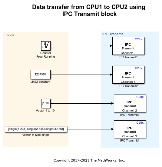
此示例使用四种不同的频道在核心之间传输和接收数据。The following data is transmitted from CPU1 to CPU2:
标量UINT16计数器值从通道0发送
uint32类型的标量数据从通道1发送
A vector [1x10] of type uint16 is sent from channel 2
单个单个矢量[1x3]从通道3发送
TI F2837XD的CPU1模型(C28x)
打开c2837xd_ipc_cpu1_tx.model, and click构建,部署和启动在下面硬件标签或按下Ctrl+B要在CPU1上构建和下载可执行文件。
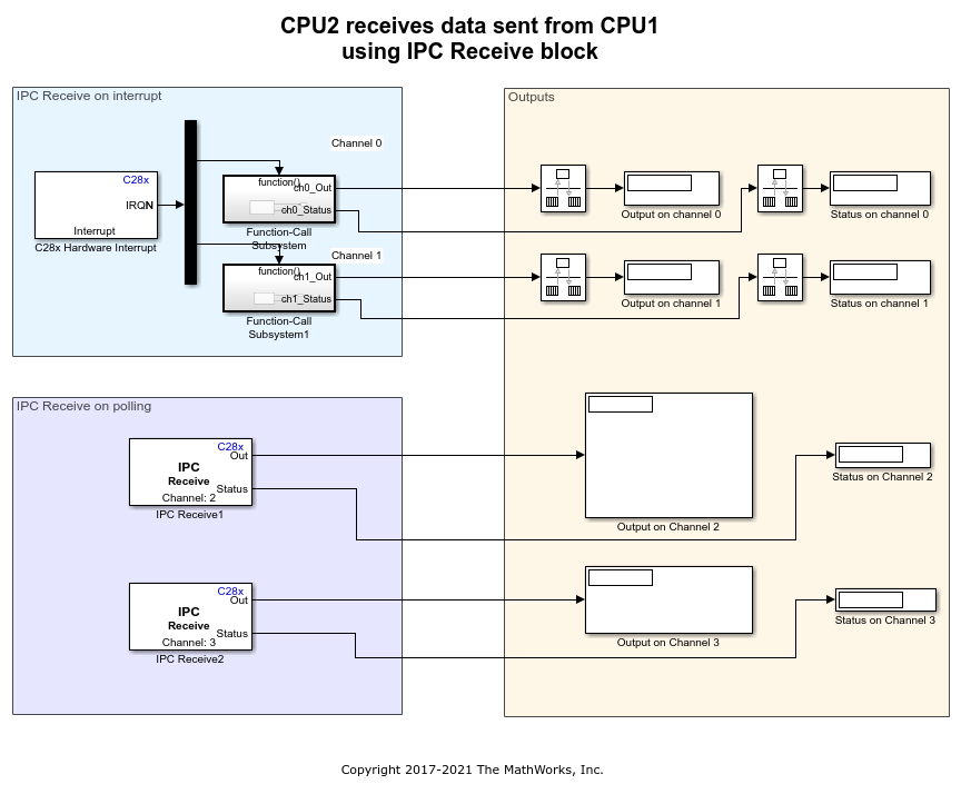
CPU2 model for TI F2837xD (C28x)
CPU2在轮询和中断模式下使用IPC接收块接收数据。
1。打开c2837xd_ipc_cpu2_rx.模型。
2.在这方面配置参数窗口,点击硬件Implementation并导航到Target hardware resources>External modeand set theSerial portparameter to the COM port atDevice Manager>Ports(COM&LTP)在Windows中。有关更多信息,请参阅Parameter Tuning and Signal Logging with Serial Communication。
3.打开硬件标签并单击监控和曲调。
4。Observe the output data using display blocks. The data received in CPU2 must match the data transmitted from CPU1.
笔记: The channel number of the IPC Receive block on the reading CPU must match the channel number of the IPC Transmit block on the writing CPU.
记忆细节
对于处理器间通信:
For scalar data transfers, message RAMs will be used. The current memory settings in the linker file are:
CPU2TocPU1RAM:Origin = 0x03F800,长度= 0x000400
cpu1tocpu2ram:origin = 0x03fc00,长度= 0x000400
对于向量数据传输,使用全局共享RAM(2x16k)的两个块。链接器文件中的当前内存设置是:
RAMGS_IPCBuffCPU1 : origin = 0x00C000, length = 0x001000
RAMGS_IPCBUFFCPU2:源= 0x00d000,长度= 0x001000
You can access the linker file by browsing to配置参数>硬件Implementation>Target hardware resources>构建选项。
对于使用IPC块的较大数据传输,必须使用链接文件增加内存。为了增加IPC内存大小,为RAMGS_IPCBUFFCPU1和RAMGS_IPCBUFFCPU2分配更多内存。两种情况下存储器的大小必须是相同的。
For dual motor control using IPC blocks, see使用C2000处理器控制PMSM加载双电机(DYNO)。In this example,c28379dpmsmfocdual_cpu1_ert.slx.andc28379dpmsmfocdual_cpu2_ert.slx.models communicate using IPC.
任务2 - 使用IPC块在TI F2838x(C28x)和TI F2838x(ARM Cortex -M4)之间的CPU1,CPU2之间进行通信
此示例的此任务配置了Texas Instruments™F2838x ControlCard。F2838x是一个多核处理器。您可以为三个核心闪烁三种不同的型号。
此示例使用四种不同的频道在核心之间传输和接收数据。
自由运行的计数器数据从CPU1传输到CPU2。数据通过四个通道(0,1,2,3)以四种不同的样本速率传输
The data is received at CPU2 using IPC receive blocks. The channel numbers and sample time are configured to match the channel numbers and sample time used in IPC Transmit blocks in CPU1. The received data is then transferred from CPU2 to ARM Cortex - M4.
使用IPC接收块在ARM Cortex-M4处接收数据。通道编号和采样时间被配置为匹配CPU2中IPC发送块中使用的信道编号和采样时间。然后将接收的数据从ARM Cortex-M4转移到CPU1。
Run the CPU1 model in External mode and compare the data sent to CPU2 with the data received from ARM Cortex - M4.
In order to run the example. Download the CPU2 model for TI F2838x (C28x) and ARM Cortex -M4 model ( TI F2838x (ARM Cortex - M4)) and then run CPU1 model for TI F2838x (C28x) in External mode.
TI F2838x的CPU2模型(C28x)
打开CPU2 model,然后点击构建,部署和启动在下面硬件标签或按下Ctrl+Bto build and download the executable file on CPU2.
ARM Cortex - M4 model for TI F2838x (ARM Cortex - M4)
打开ARM Cortex-M4模型,然后点击构建,部署和启动在下面硬件标签或按下Ctrl+B在ARM Cortex - M4上构建和下载可执行文件。
CPU1模型for TI F2838x (C28x)
1。打开CPU1模型。
2。In the配置参数窗口,点击硬件Implementation并导航到Target hardware resources > External modeand set theSerial portparameter to the COM port atDevice Manager > Ports (COM <P)in Windows. For more information, seeParameter Tuning and Signal Logging with Serial Communication。
3.打开硬件标签并单击监控和曲调。
4。使用显示块观察输出数据。与传输到CPU2的数据相比,从ARM Cortex-M4接收的数据将被延迟值。
记忆细节
For inter-processor communication between CPU1 and CPU2,
For scalar data transfers, message RAMs will be used. The current memory settings in the linker file are:
CPU1TOCPU2RAM: origin = 0x03A000, length = 0x000800
cpu2tocpu1ram:origin = 0x03b000,长度= 0x000800
对于向量数据传输,使用全局共享RAM(2x16k)的两个块。链接器文件中的当前内存设置是:
RAMGS_IPCBUFFCPU1:源= 0x00d000,长度= 0x001000
RAMGS_IPCBUFFCPU2:源= 0x00E000,长度= 0x001000
对于使用IPC块的较大数据传输,必须使用链接文件增加内存。You can access the linker file by browsing to配置参数>硬件实现>目标硬件资源>构建选项。为了增加IPC内存大小,为RAMGS_IPCBUFFCPU1和RAMGS_IPCBUFFCPU2分配更多内存。两种情况下存储器的大小必须是相同的。
For inter-processor communication between CPU1/CPU2 and ARM Cortex - M4, as global shared RAM is not available, IPC message RAM is used. The amount of data transfer between CPU1/CPU2 and ARM Cortex - M4 is limited by the size of the message RAMs available.
The current message RAM settings in the linker file are:
CPUTOCMRAM : origin = 0x039000, length = 0x000800
CMTOCPURAM : origin = 0x038000, length = 0x000800
For information about IPC blocks, see:
You can also select a web site from the following list:
Americas
- América Latina(Español)
- Canada(English)
- United States(English)