在上一个视频中,我们讨论了这种体系结构,该体系结构实现了PWM控制的雄鹿转换器,以不同的速度控制BLDC电机。在此视频中,我们将向您展示PWM Control的另一种实现,我们还在第三款电动机控制技术谈话视频中进行了详细讨论。
使第二个体系结构与第一个架构不同的原因是,它不使用Buck转换器降低直流源电压,而是直接调节三相电压。现在,我们将从该模型开始,该模型已经包含子系统,例如控制器,三相逆变器,BLDC和传感器。随时查看我们以前的视频,以了解如何使用Simscape Electrical库中的块来构建这些子系统。
在第一个体系结构中,我们实现了PWM控制器rol under the buck converter subsystem. In this new architecture that we’re going to build, we’ll implement PWM control under commutation logic, where we compute the switching pattern to be sent to the three-phase inverter. So, let’s go into this subsystem.
Here, we see what we eventually want to achieve with this implementation. We want to modulate the three-phase voltages by taking the DC source voltage, which is 500 volts in this case, and using it to switch the voltages of the commutating phases between these two values— plus or minus half the DC source voltage. This way the effective voltage seen by the motor gets averaged.
我们已经拥有的当前逻辑代表了我们在第三次视频中构建的逻辑,但没有任何阶段切换。如果我们使用了这种逻辑,则通勤阶段将在整个相应扇区中用恒定电压通电。为了使用PWM控件正确切换相位,如下所示,现在我们将修改此逻辑。
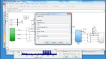
Note that during each PWM period, the commutating phases are switched between + and −250 volts in a complementary fashion. For example, during this period where we commutate phases A and B, while we drive phase A with positive voltage, phase B is driven with negative voltage and vice versa. To implement this, we first duplicate all of these blocks with the switching patterns and then reverse the bits of the commutating phases. For example, to reverse this switching pattern, we simply flip the 1s and 0s in the commutating phases A and C. After completing this for the remaining switching patterns, now we add a PWM generator and a switch and connect these together like this.
PWM发电机的输入是由控制器计算的占空比。因此,我们上升并输入该信号到换向逻辑,该逻辑会自动在子系统中创建输入端口。然后,我们设置PWM频率和样品时间,该时间已在MATLAB工作区中预定义。接下来,我们将开关阈值更新为正值。这样,在PWM信号的打开时间期间,我们将根据当前扇区以及PWM循环的其余部分传递此部分的开关模式,我们将通过互补模式。
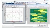
现在,此逻辑可以正确地切换相位。要查看它是否正常工作,让我们模拟该模型并查看已记录的信号。我们看到速度跟踪非常好。测得的速度以橙色显示,这使得很难看到绿色所需的速度。该图显示了500伏的直流电源电压,在这里,我们看到它如何在通勤阶段的 +和-250伏之间切换。由于这种切换,电动机将看到平均电压,该电压与虚线所示的电压相似。
Note that the back-EMF voltage seen in the non-commutating phase helps us estimate the approximate effective voltage that is seen by the motor. For example, right before phase A is commutated, we read a back-Emf voltage of −25 volts. So, we can say that the effective phase A voltage seen by the motor is around −25 volts throughout this region. Using the same logic, we can show the approximate back-EMF voltages for phases A, B, and C as seen in here with the dashed lines.
总而言之,在此视频中,我们构建了一个模型来实现PWM控件,以直接将三相电压调节到BLDC电动机以不同的值控制其速度。有关BLDC电动机控制的更多信息,请查看此视频下面的链接。