 Cleve’s Corner: Cleve Moler on Mathematics and Computing
 Loren on the Art of MATLAB
 Steve on Image Processing with MATLAB
 Guy on Simulink
 Deep Learning
 Developer Zone
 Stuart’s MATLAB Videos
 Behind the Headlines
 File Exchange Pick of the Week
 Hans on IoT
 Student Lounge
 MATLAB Community
 MATLAB ユーザーコミュニティー
Continuous Time Integrator
One of the ways I think of Simulink is as a graphical interface to the solvers. Moreover, when I think of the solvers, I usually think of the continuous time solvers and the integrator block. In this post, I will show you some of the capabilities of the continuous time integrator that you might not know about. I will also demonstrate how I keep track of the ports on the integrator block.
The Continuous State
The continuous time Integrator block is the building block for ODEs/continuous time systems. Labeing the input and output of the Integrator block keeps my signals organized whendrawing ODEs.
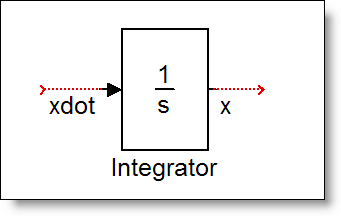
Labeling the signals is also beneficial when adding reset, initial condition, saturation, and state ports to the block.
External Reset
TheExternal resetsignal (second inport) triggers the integrator state to reset to the initial condition value. External reset can be set torising, falling, either edge, level or level hold.
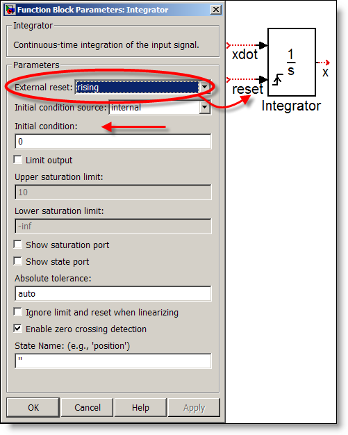
The internal initial condition is not always the right value at the time the state resets. Often, the new state value comes from a calculation in the model via the IC port.
External Initial Condition
Set theInitial condition sourceas external to provide the IC value via signal.
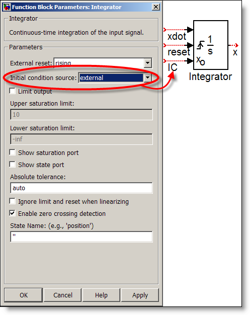
This state (x) is set to this signal value when the reset signal triggers. To provide an initial condition at time Tstart, add anIC block(from the Signal Attributes library) inline with the signal that calculates the IC.
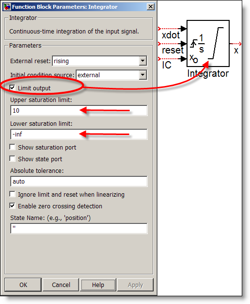
Limit Output (state saturation)
TheLimit outputcheck box enables theUpper saturation limitandLower saturation limitparameters. This also adds the saturation icon to the block. Note, it is easy to mistake this as an integral signal, however, this actually indicates that the state has an upper and/or lower limit.
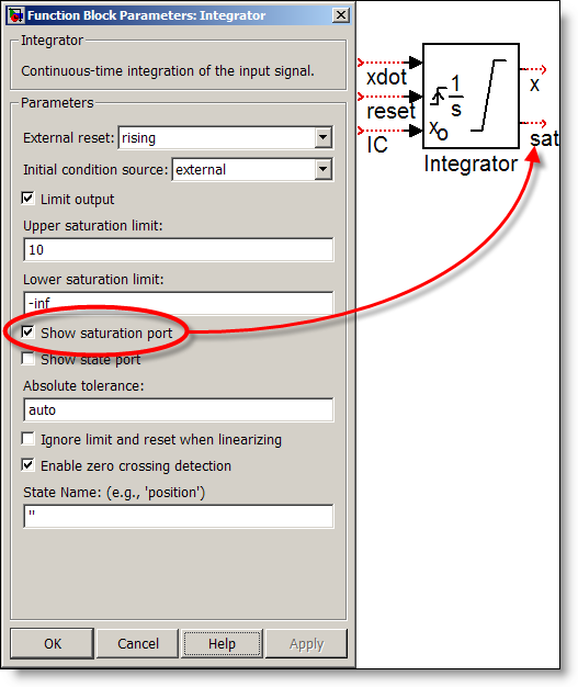
Saturation Port
Check theShow saturation portparameter to add a second output, the saturation port. The signal from this port is 0 when the value of the state is within the limits, and 1 when the value of the state is at the limit. This transition from 0 to 1 and 1 to 0 can be used as rising and falling edges triggers.
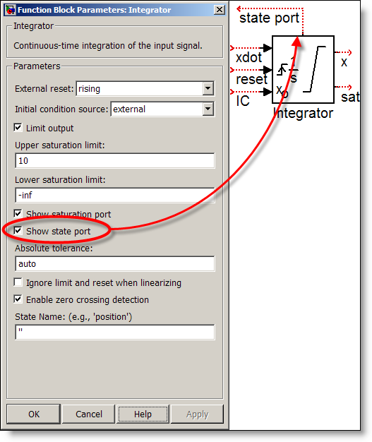
State port
ClickingShow state portadds a special port on the top of the block. The state port provides a way to model self-resetting integrators and performing state hand off between enabled subsystems without creating algebraic loops.
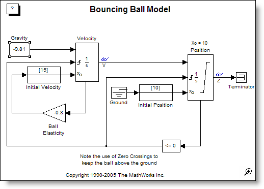
Bouncing Ball Demo
The bouncing ball demo combines some of these integrator block capabilities.
点击这张图片sldemo_b的web视图ounce model.
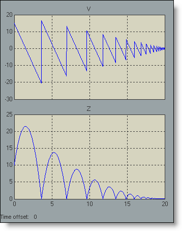
Note the use of the IC block to provide an Initial Velocity and Initial Position for the bouncing ball. The IC block feeds through its input when T≠Tstart. This allows the ball to reset the velocity state (V) to -0.8 * V when the position of the ball hits zero. This use of the state port prevents the algebraic loop connecting the velocity state to the initial state value and reset signals. Here are the simulation results.
Now it’s your turn
I got into the habit of labeling the ports on the integrator while I was a trainer teaching Simulink. It was always helpful in keeping the model organized. Have you used these features of the Integrator block? What did your model do? Leave me acomment here.


Comments
To leave a comment, please clickhereto sign in to your MathWorks Account or create a new one.