LTE CRC Decoder
Detect errors in input samples using checksum
- Library:
Wireless HDL Toolbox / Error Detection and Correction
Description
TheLTE CRC Decoderblock calculates a cyclic redundancy check (CRC) and compares it with the appended checksum, for each frame of streaming data samples. You can select from the polynomials specified by LTE standard TS 36.212[1]. The block provides a hardware-optimized architecture and interface.
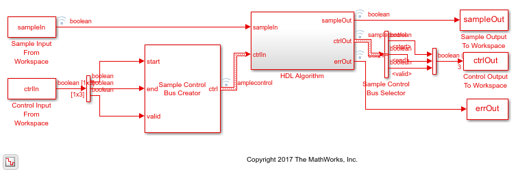
This block uses a streaming sample interface with a bus for related control signals. This interface enables the block to operate independently of frame size, and to connect easily with other Wireless HDL Toolbox™ blocks. The block accepts and returns a value representing a single sample, and a bus containing three control signals. These signals indicate the validity of each sample and the boundaries of the frame. To convert a matrix into a sample stream and these control signals, use theFrame To Samplesblock or thewhdlFramesToSamplesfunction. For a full description of the interface, seeStreaming Sample Interface.
Ports
Input
Output
Parameters
Model Examples
Algorithms
When you use vector or integer input, the block implements a parallel CRC algorithm[2]. The implementation is the same as the algorithm used by the Communications Toolbox™ blocksGeneral CRC Generator HDL OptimizedandGeneral CRC Syndrome Detector HDL Optimized.
To provide high throughput for modern communications systems, the block implements the CRC algorithm with a parallel architecture. This architecture recursively calculatesMbits of a CRC checksum for eachWinput bits. At the end of the frame, the final checksum result is appended to the message. For a polynomial length ofM, the recursive checksum calculation forWbits in parallel is
FWis anM-by-Mmatrix that selects elements of the current state for the polynomial calculation with the new input bits.Dis anM-element vector that provides the new input bits, ordered in relation to the generator polynomial and padded with zeros. The block implements the (×) with logical AND and (+) with logical XOR.

Latency
This waveform shows a 40-sample frame, input two samples at a time, encoded with a CRC16 polynomial. There is no gap between input frames. The output stream has removed the checksum, so there are eight cycles between output frames. The latency of the decoder is3*CRCLength/InputSize+ 5, assuming contiguous valid input samples.

References
[1] 3GPP TS 36.212. "Multiplexing and channel coding."3rd Generation Partnership Project; Technical Specification Group Radio Access Network; Evolved Universal Terrestrial Radio Access (E-UTRA). URL:https://www.3gpp.org.
[2] Campobello, Giuseppe, Giuseppe Patane, and Marco Russo. "Parallel CRC Realization."IEEE计算机. Vol. 52, No. 10, October 2003, pp. 1312–1319.
Extended Capabilities
Version History
You can also select a web site from the following list:
Americas
- América Latina(Español)
- Canada(English)
- United States(English)
Europe
- Belgium(English)
- Denmark(English)
- Deutschland(Deutsch)
- España(Español)
- Finland(English)
- France(Français)
- Ireland(English)
- Italia(Italiano)
- Luxembourg(English)
- Netherlands(English)
- Norway(English)
- Österreich(Deutsch)
- Portugal(English)
- Sweden(English)
- Switzerland
- United Kingdom(English)