 Cleve’s Corner: Cleve Moler on Mathematics and Computing
 Loren on the Art of MATLAB
 Steve on Image Processing with MATLAB
 Guy on Simulink
 Deep Learning
 Developer Zone
 Stuart’s MATLAB Videos
 Behind the Headlines
 File Exchange Pick of the Week
 汉斯在物联网上
 学生休息室
学生休息室 MATLAB Community
 matlabユーザーコミュニティー
How Do Autonomous Systems “See”?
Sebastian Castro回到谈论在自治系统传感器吗s, supported by a few example algorithms and student competitions that use low-cost hardware platforms.
Introduction
There are many challenges around the world that focus on learning autonomous perception and navigation using low-cost ground vehicle platforms. Here are a few that we support, which consist of similar tasks:
Ourprevious blog postcovered the Rose-Hulman High School Autonomous Vehicle Challenge. In this post, we will dive deeper into theTurtleBot3 AutoRace。This student competition contains a ready-to-gosimulation packageand aset of tutorials。
TurtleBot3 is also designed to be an educational low-cost platform for the机器人操作系统(ROS)。ROS is a software framework that, among many things, lets users easily switch between simulation and hardware. As we have discussed in aprevious blog post, MATLAB and Simulink has an interface to ROS. This made it possible for us to collect data from the AutoRace simulation and put together some quick examples.
ROS is also known for containing specialized message types that represent common sensors used in autonomous systems. At the same time, MATLAB and Simulink have toolboxes forcomputer vision,motion planning, andautomated driving。So, in the rest of this post I will bridge these two tools by exploring common sensor types a few examples:
- Vision sensors:Various types of cameras (mono vs. stereo, color vs. infrared, etc.)
- Line-of-sight sensors:超声传感器,雷达和激光雷达。
First, we can download the TurtleBot3 AutoRace software packages and start up the Gazebo simulator.
$ roslaunch turtlebot3_gazebo turtlebot3_autorace.launch

Then, we can connect MATLAB to the simulator using ROS. Since I am using a Windows host and a Linux virtual machine, I am connecting to a ROS master with a specific IP address as shown below.
rosinit('192.168.119.129');
Camera Example: Lane Detection
Let’s receive an image from the simulator.
imgSub = rossubscriber('/camera/image'); imgMsg = receive(imgSub); rgbImg = readImage(imgMsg);
All the student competitions listed above have a lane detection and following component, so let’s use images to try detecting some lanes. A typical workflow is:
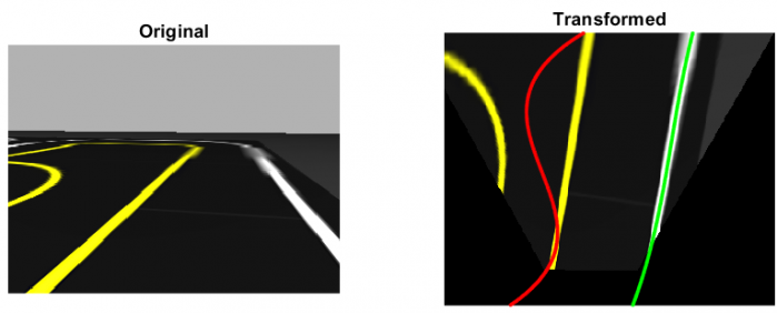
- Transform image to a bird’s-eye view
- Segment the image
- Detect the lanes
- Create a control algorithm to follow (or not follow) the lanes
Bird的眼视图通常用于使车道检测更加容易,因为它通过显示图像的自上而下的视图来消除相机的“透视”效果。要执行此转换,我们需要计算一个转换矩阵,该矩阵在图像的像素上执行旋转和/或翻译。为此,您可以:
- Obtain intrinsic (focal length, distortion, etc.) and extrinsic (location of camera on the vehicle) parameters for the camera, and then calculate the transformation matrix
- Estimate a transformation matrix by mapping 4 points on the image to 4 known points in the real world
To obtain the camera intrinsic parameters, you can either view the manufacturer datasheet orcalibrate to a known pattern— usually a checkerboard. In this example, I took the second method which involvedmanually selecting pointsand mapping them to a known “truth” value in the bird’s-eye view. TheestimateGeometricTransformfunction was key in this step.
tform = estimateGeometricTransform(points,truth,'projective'); warpedImg = imwarp(rgbImg,tform); subplot(1,2,1) imshow(rgbImg); subplot(1,2,2) imshow(flipud(warpedImg));

To segment the image, you can usecolor thresholding。为了使事情变得更轻松,这些学生竞赛使用颜色来区分左右车道边界。在汽车中,车道是黄色和白色的,因此我们可以校准和定义两组颜色阈值。
yellowIdx = (warpedImg(:,:,1) > 100 & warpedImg(:,:,3) < 100); whiteIdx = (warpedImg(:,:,1) > 100 & warpedImg(:,:,3) > 100);

Finally, you can use the location of the pixels to approximate the lanes as mathematical equations — typically polynomials. A straight lane can be represented as a line (or degree 1 polynomial), but curved lanes benefit from higher order polynomials like quadratic or cubic. To reduce the number of pixels for curve fitting, I firstskeletonized the linesto make them one pixel wide.
polyOrder = 3; [ry,cy] = find(bwskel(yellowIdx)); yellowPoly = polyfit(ry,cy,polyOrder);

There is also the problem of multiple lanes in an image. So, instead of fitting a polynomial to all the pixels that meet the given color threshold, you can apply techniques likerandom sample consensus (RANSAC)消除异常值和生产tter results.
polyOrder = 3; numOutliers = 50; [ry,cy] = find(bwskel(yellowIdx)); yellowPoly = fitPolynomialRANSAC([ry cy],polyOrder,numOutliers);
Lanes detected with regular polynomial fit, showing the effect of outliers
 Lanes detected with RANSAC, showing the elimination of outliers
For more advanced lane detection and following applications, you may want to look at some examples in Automated Driving System Toolbox:
Lidar Example: Localization and Mapping
Unlike images, measurements from line-of-sight sensors do not contain color or intensity information. However, they are better at directly measuring distance and velocity between the vehicle and potential obstacles or landmarks.
超声波传感器、雷达和激光雷达are fundamentally similar, except they use sound, radio waves, and light (respectively). Since light is much faster than sound, lidar can produce higher-resolution data, both in 2D and 3D. On the other hand, ultrasonic and radar sensors are less expensive, have a longer operating range, and are more robust to weather conditions.
视线传感器用于两个主要任务:
- Obstacle detection
- Localization and mapping
在此示例中,我们将与LiDAR一起演示。首先,让我们从模拟激光雷达传感器中收到扫描并将其转换为lidar scan objectfor convenience.
scanSub = rossubscriber('/scan'); lidar = lidarScan(receive(scanSub));
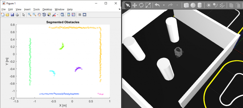
Obstacle detectiongenerally involves separating the drivable terrain from the obstacles, if needed, and then using machine learning techniques such as clustering to gain more information about the structure of the environment. For more information, refer tothis documentation page。
% Convert 2D scan to 3D point cloud and perform obstacle segmenting using Euclidean distance clustering ptCloud = pointCloud([lidar.Cartesian zeros(size(lidar.Cartesian,1),1)]); minDist = 0.25; [labels,numClusters] = pcsegdist(ptCloud,minDist);
As forlocalization, the simplest approach is “dead reckoning”, or counting the number of times the vehicle’s wheels have turned. Since this process requires integrating speed measurements to estimate position, it is highly sensitive to wheel slip and sensor noise/drift. Lidar based localization methods are more complicated and computationally expensive, but because they do not depend on the entire history of sensor readings, they are better at avoiding drift in the estimated vehicle position.
Localization with lidar depends on whether or not the map already exists:
- If the map is known, you can use probabilistic methods like粒子过滤器to figure out the most likely locations that would produce the current reading.
- If the map is not known, you can use optimization methods likescan matchingto figure out how far you moved between two consecutive scans.
% Get first scan lidar1 = lidarScan(receive(scanSub)); % Move robot velMsg.Linear.X = 0.1; velMsg.Angular.Z = 0.25; send(velPub,velMsg); pause(1); velMsg.Linear.X = 0; velMsg.Angular.Z = 0; send(velPub,velMsg); % Get second scan lidar2 = lidarScan(receive(scanSub)); % Perform scan matching relPoseScan = matchScans(lidar2,lidar1)

Scan matching additionally lets you perform simultaneous localization and mapping (SLAM). By taking a sequence of lidar measurements, you can estimate both the vehicle trajectory and obstacle positions in the map that most likely would generate these measurements. One way to do this is by building and optimizing a graph of robot poses (position and orientation) over time, which is known as graph-based SLAM and isavailable in Robotics System Toolbox。
Below is the result of collecting 45 seconds worth of data and estimating the robot trajectory and map only from lidar information. This is known as offline SLAM, in contrast to online SLAM which would be doing the same but with live data as the vehicle is driving.

% Define the LidarSLAM object maxRange = 2; % meters resolution = 25; % cells per meter slam = robotics.LidarSLAM(resolution,maxRange); slam.LoopClosureThreshold = 350; slam.LoopClosureSearchRadius = 5; % Build and optimize the pose graph numIters = numel(scansSampled); for idx = 1:numIters addScan(slam,scansSampled(idx)); end % Export the final results as an Occupancy Grid [slamScans, slamPoses] = scansAndPoses(slam); map = buildMap(slamScans, slamPoses, resolution, maxRange);

In practice, it is common to perform sensor fusion, or combine the readings from multiple sensors, using techniques such asKalman filtering。This lets algorithms use the relative advantages of various sensors, provides redundant information in case some sensors produce inaccurate readings, and allows for more robust tracking of detected objects through time.
Now that you have a map, you can refer to the following examples to see how to navigate in this path:
- Path planning in environments of different complexity
- Automated parking valetin MATLABandin Simulink
What’s Next?
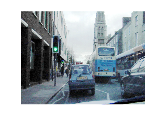
There is much more you can do with these sensors. One topic we did not discuss here is the use of machine learning to classify and locate other objects of interest — for example, traffic signs, pedestrians, or other vehicles. In fact, other student competitions like theAI Driving Olympics (AI-DO)are encouraging such solutions over the more “traditional” techniques described above.
In the examples above, we used ROS to stream sensor data to a separate computer that is running MATLAB — so the processing is done off-board. Small, low-cost platforms often cannot run a full install of MATLAB. Depending on the type of algorithms you create and hardware you are targeting, you can take advantage of C/C++ code generation from MATLAB and Simulink, as well as its hardware support packages. This lets you use MATLAB and Simulink for prototyping and design without having to later rewrite your design in a different language so it runs on your target system.
TheTurtleBot3 platform, for instance, has aRaspberry Pi 3 Model Brunning Linux and ROS. So, if your algorithm is written with functionality and syntax that supports code generation, you can follow a workflow similar tothis exampleand get your MATLAB code or Simulink models running standalone on the robot or autonomous vehicle.
If you have any questions on anything discussed here, feel free to leave us a comment or get in touch with us viaemailorFacebook。
- Category:
- Automotive,
- Education,
- MATLAB,
- Robotics


Comments
To leave a comment, please clickhereto sign in to your MathWorks Account or create a new one.