Configure Monocular Fisheye Camera
This example shows how to convert a fisheye camera model to a pinhole model and construct a corresponding monocular camera sensor simulation. In this example, you learn how to calibrate a fisheye camera and configure amonoCameraobject.
Overview
To simulate a monocular camera sensor mounted in a vehicle, follow these steps:
Estimate the intrinsic camera parameters by calibrating the camera using a checkerboard. The intrinsic parameters describe the properties of the fisheye camera itself.
Estimate the extrinsic camera parameters by calibrating the camera again, using the same checkerboard from the previous step. The extrinsic parameters describe the mounting position of the fisheye camera in the vehicle coordinate system.
Remove image distortion by converting the fisheye camera intrinsics to pinhole camera intrinsics. These intrinsics describe a synthetic pinhole camera that can hypothetically generate undistorted images.
Use the intrinsic pinhole camera parameters and the extrinsic parameters to configure the monocular camera sensor for simulation. You can then use this sensor to detect objects and lane boundaries.
Estimate Fisheye Camera Intrinsics
To estimate the intrinsic parameters, use a checkerboard for camera calibration. Alternatively, to better visualize the results, use theCamera Calibrator(Computer Vision Toolbox)app. For fisheye camera, it is useful to place the checkerboard close to the camera, in order to capture large noticeable distortion in the image.
% Gather a set of calibration images.images = imageDatastore(fullfile(toolboxdir('vision'),'visiondata',...'calibration','gopro')); imageFileNames = images.Files;% Detect calibration pattern.[imagePoints, boardSize] = detectCheckerboardPoints(imageFileNames);% Generate world coordinates of the corners of the squares.squareSize = 0.029;% Square size in metersworldPoints = generateCheckerboardPoints(boardSize, squareSize);% Calibrate the camera.I = readimage(images, 1); imageSize = [size(I, 1), size(I, 2)]; params = estimateFisheyeParameters(imagePoints, worldPoints, imageSize);
Estimate Fisheye Camera Extrinsics
To estimate the extrinsic parameters, use the same checkerboard to estimate the mounting position of the camera in the vehicle coordinate system. The following step estimates the parameters from one image. You can also take multiple checkerboard images to obtain multiple estimations, and average the results.
% Load a different image of the same checkerboard, where the checkerboard% is placed on the flat ground. Its X-axis is pointing to the right of the% vehicle, and its Y-axis is pointing to the camera. The image includes% noticeable distortion, such as along the wall next to the checkerboard.imageFileName = fullfile(toolboxdir('driving'),'drivingdata','checkerboard.png'); I = imread(imageFileName); imshow(I) title('Distorted Checkerboard Image');

[imagePoints, boardSize] = detectCheckerboardPoints(I);% Generate coordinates of the corners of the squares.squareSize = 0.029;% Square size in metersworldPoints = generateCheckerboardPoints(boardSize, squareSize);% Estimate the parameters for configuring the monoCamera object.% Height of the checkerboard is zero here, since the pattern is% directly on the ground.originHeight = 0; [pitch, yaw, roll, height] = estimateMonoCameraParameters(params.Intrinsics,...imagePoints, worldPoints, originHeight);
构造一个合成Undis针孔照相机torted Image
% Undistort the image and extract the synthetic pinhole camera intrinsics.[J1, camIntrinsics] = undistortFisheyeImage(I, params.Intrinsics,'Output','full'); imshow(J1) title('Undistorted Image');

% Set up monoCamera with the synthetic pinhole camera intrinsics.% Note that the synthetic camera has removed the distortion.sensor = monoCamera(camIntrinsics, height,'pitch', pitch,'yaw'偏航,'roll', roll);
Plot Bird's Eye View
Now you can validate themonoCameraby plotting a bird's-eye view.
% Define bird's-eye-view transformation parametersdistAheadOfSensor = 6;% in metersspaceToOneSide = 2.5;% look 2.5 meters to the right and 2.5 meters to the leftbottomOffset = 0.2;% look 0.2 meters ahead of the sensoroutView = [bottomOffset, distAheadOfSensor, -spaceToOneSide, spaceToOneSide]; outImageSize = [NaN,1000];% output image width in pixelsbirdsEyeConfig = birdsEyeView(sensor, outView, outImageSize);% Transform input image to bird's-eye-view image and display itB = transformImage(birdsEyeConfig, J1);% Place a 2-meter marker ahead of the sensor in bird's-eye viewimagePoint0 = vehicleToImage(birdsEyeConfig, [2, 0]); offset = 5;% offset marker from text label by 5 pixelsannotatedB = insertMarker(B, imagePoint0 - offset); annotatedB = insertText(annotatedB, imagePoint0,'2 meters'); figure imshow(annotatedB) title('Bird''s-Eye View')
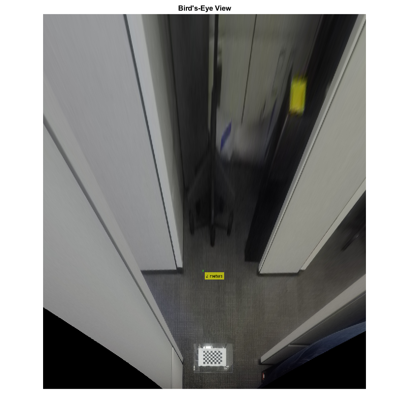
The plot above shows that the camera measures distances accurately. Now you can use the monocular camera for object and lane boundary detection. See theVisual Perception Using Monocular Cameraexample.
See Also
Apps
- Camera Calibrator(Computer Vision Toolbox)
Functions
estimateMonoCameraParameters|detectCheckerboardPoints(Computer Vision Toolbox)|estimateFisheyeParameters(Computer Vision Toolbox)|generateCheckerboardPoints(Computer Vision Toolbox)|undistortFisheyeImage(Computer Vision Toolbox)
Objects
Related Topics
Select a Web Site
Choose a web site to get translated content where available and see local events and offers. Based on your location, we recommend that you select:.
Selectweb siteYou can also select a web site from the following list:
Americas
- América Latina(Español)
- Canada(English)
- United States(English)
Europe
- Belgium(English)
- Denmark(English)
- Deutschland(Deutsch)
- España(Español)
- Finland(English)
- France(Français)
- Ireland(English)
- Italia(Italiano)
- Luxembourg(English)
- Netherlands(English)
- Norway(English)
- Österreich(Deutsch)
- Portugal(English)
- Sweden(English)
- Switzerland
- United Kingdom(English)