firceqrip
Constrained equiripple FIR filter
Syntax
B = firceqrip(n,Fo,DEV)
B = firceqrip(…,“坡”,r)
B = firceqrip('minorder',[Fp Fst],DEV)
B = firceqrip(...,'passedge')
B = firceqrip(...,'stopedge')
B = firceqrip(...,'high')
B = firceqrip(...,'min')
B = firceqrip(...,'invsinc',C)
B = firceqrip(...,'invdiric',C)
Description
B = firceqrip(n,Fo,DEV)designs an ordernfilter (filter length equaln+ 1) lowpass FIR filter with linear phase.
firceqripproduces the same equiripple lowpass filters thatfirpmproduces using the Parks-McClellan algorithm. The difference is how you specify the filter characteristics for the function.
The input argumentFospecifies the frequency at the upper edge of the passband in normalized frequency (0<Fo<1). The two-element vectordevspecifies the peak or maximum error allowed in the passband and stopbands. Enter[d1 d2]fordevwhered1sets the passband error andd2sets the stopband error.
B = firceqrip(…,“坡”,r)uses the input keyword 'slope' and input argumentrto design a filter with a nonequiripple stopband.ris specified as a positive constant and determines the slope of the stopband attenuation in dB/normalized frequency. Greater values ofrresult in increased stopband attenuation in dB/normalized frequency.
B = firceqrip('minorder',[Fp Fst],DEV)designs filter with the minimum number of coefficients required to meet the deviations inDEV= [d1d2] while having a transition width no greater thanFst–Fp, the difference between the stopband and passband edge frequencies. You can specify'mineven'or'minodd'instead of'minorder'to design minimum even order (odd length) or minimum odd order (even length) filters, respectively. The'minorder'option does not apply when you specify the'min'(minimum-phase),'invsinc', or the'invdiric'options.
B = firceqrip(...,'passedge')designs a filter whereFo指定的频率通带明星ts to rolloff.
B = firceqrip(...,'stopedge')designs a filter whereFospecifies the frequency at which the stopband begins.
B = firceqrip(...,'high')designs a high pass FIR filter instead of a lowpass filter.
B = firceqrip(...,'min')designs a minimum-phase filter.
B = firceqrip(...,'invsinc',C)设计低通滤波器费尔ter whose magnitude response has the shape of an inverse sinc function. This may be used to compensate for sinc-like responses in the frequency domain such as the effect of the zero-order hold in a D/A converter. The amount of compensation in the passband is controlled byC, which is specified as a scalar or two-element vector. The elements ofCare specified as follows:
If
Cis supplied as a real-valued scalar or the first element of a two-element vector,firceqripconstructs a filter with a magnitude response of 1/sinc(C*pi*F) whereFis the normalized frequency.If
Cis supplied as a two-element vector, the inverse-sinc shaped magnitude response is raised to the positive powerC(2). If we setP=C(2),firceqripconstructs a filter with a magnitude response 1/sinc(C*pi*F)P.
If this FIR filter is used with a cascaded integrator-comb (CIC) filter, settingC(2)equal to the number of stages compensates for the multiplicative effect of the successive sinc-like responses of the CIC filters.
Note
Since the value of the inverse sinc function becomes unbounded atC=1/F, the value ofCshould be greater the reciprocal of the passband edge frequency. This can be expressed asFo<1/C. For users familiar with CIC decimators,Cis equal to 1/2 the product of the differential delay and decimation factor.
B = firceqrip(...,'invdiric',C)设计低通滤波器费尔ter with a passband that has the shape of an inverse Dirichlet sinc function. The frequency response of the inverse Dirichlet sinc function is given by
whereC,r, andpare scalars. The inputCcan be a scalar or vector containing 2 or 3 elements. IfCis a scalar,pandrequal 1. IfCis a two-element vector, the first element isCand the second element isp,[C p]. IfCis a three-element vector, the third element isr,[C p r].
Examples
To introduce a few of the variations on FIR filters that you design withfirceqrip, these five examples cover both the default syntaxb = firceqrip(n,wo,del)and some of the optional input arguments. For each example, the input argumentsn,wo, anddelremain the same.
Filter design usingfirceqrip
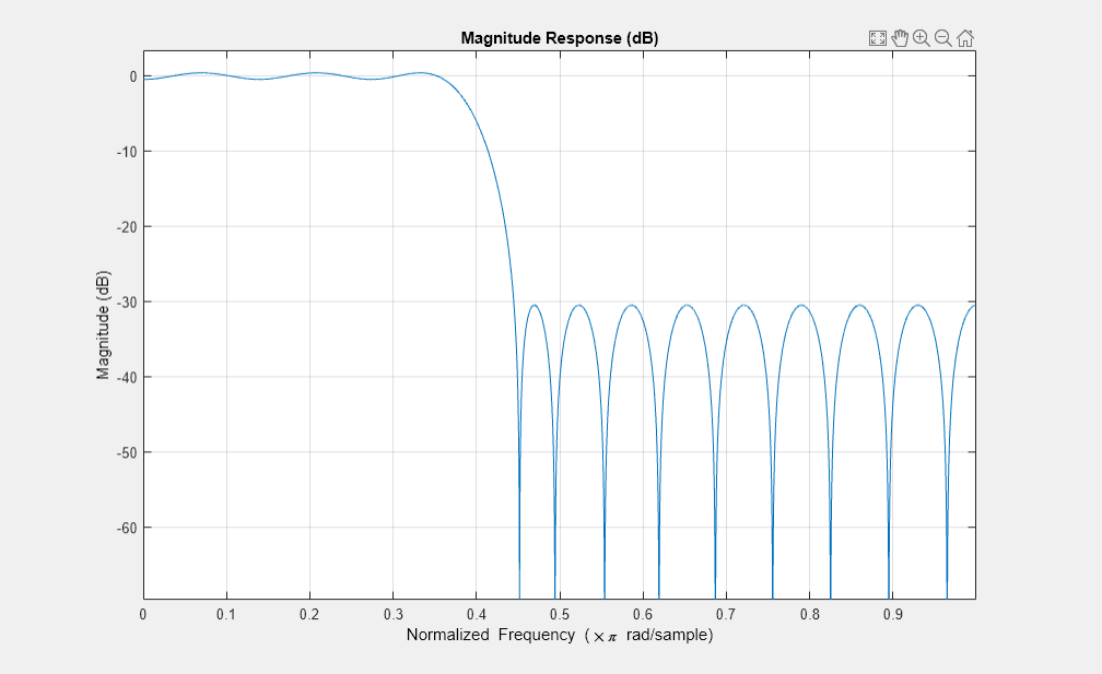
Design a 30th order FIR filter usingfirceqrip.
b = firceqrip(30,0.4,[0.05 0.03]); fvtool(b)
Design a minimum order FIR filter usingfirceqrip. The passband edge and stopband edge frequencies are 0.35
and 0.45
rad/sample. The allowed deviations are 0.02 and 1e-4.
b = firceqrip('minorder',[0.35 0.45],[0.02 1e-4]); fvtool(b)
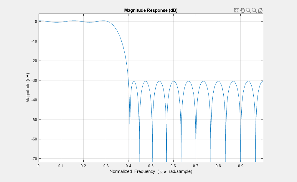
Design a 30th order FIR filter with thestopedgekeyword to define the response at the edge of the filter stopband.
b = firceqrip(30,0.4,[0.05 0.03],'stopedge'); fvtool(b)
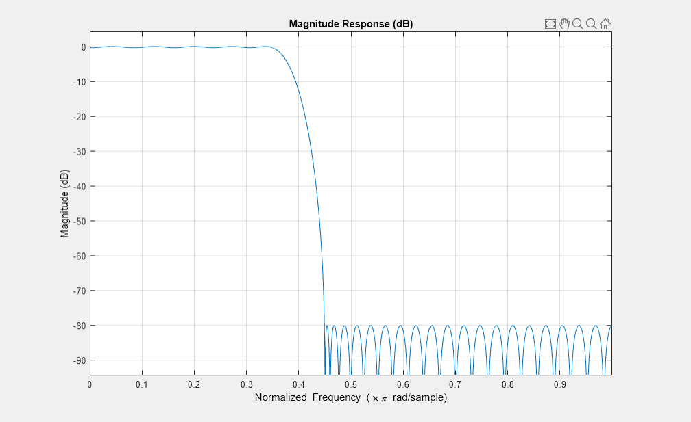
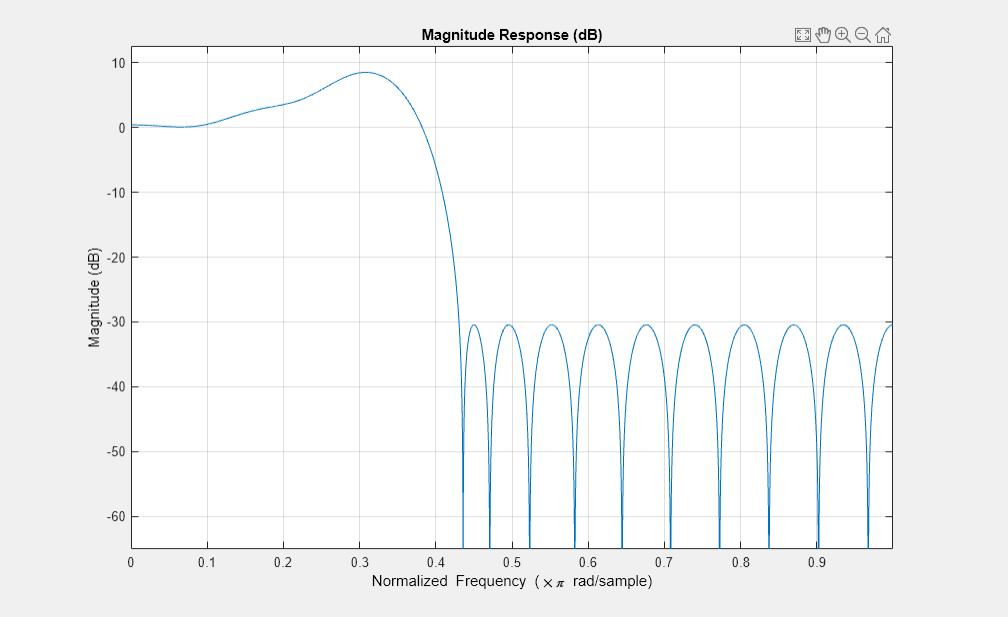
Design a 30th order FIR filter with theslopekeyword and r = 20.
b = firceqrip(30,0.4,[0.05 0.03],'slope',20,'stopedge'); fvtool(b)
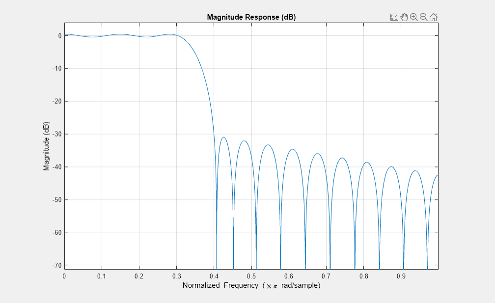
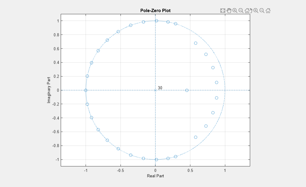
Design a 30th order FIR filter defining the stopband and specifying that the resulting filter is minimum phase with theminkeyword.
b = firceqrip(30,0.4,[0.05 0.03],'stopedge','min'); fvtool(b)
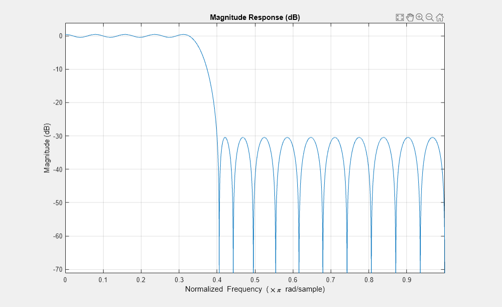
Comparing this filter to the filter in Figure 1. The cutoff frequencywo = 0.4now applies to the edge of the stopband rather than the point at which the frequency response magnitude is 0.5.
Viewing the zero-pole plot shown here reveals this is a minimum phase FIR filter - the zeros lie on or inside the unit circle, z = 1
fvtool(b,'polezero')
Design a 30th order FIR filter with theinvsinckeyword to shape the filter passband with an inverse sinc function.
b = firceqrip(30,0.4,[0.05 0.03],'invsinc',[2 1.5]); fvtool(b)
The inverse sinc function being applied is defined as 1/sinc(2*w)^1.5.
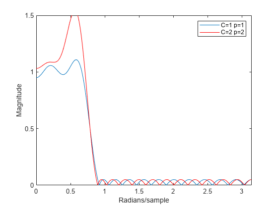
Inverse-Dirichlet-Sinc-Shaped Passband
Design two order 30 constrained equiripple FIR filters with inverse-Dirichlet-sinc-shaped passbands. The cutoff frequency in both designs is pi/4 radians/sample. SetC=1in one designC=2in the second design. The maximum passband and stopband ripple is 0.05. Setp=1in one design andp=2in the second design.
Design the filters.
b1 = firceqrip(30,0.25,[0.05 0.05],'invdiric',[1 1]); b2 = firceqrip(30,0.25,[0.05 0.05],'invdiric',[2 2]);
Obtain the filter frequency responses usingfreqz. Plot the magnitude responses.
[h1,~] = freqz(b1,1); [h2,w] = freqz(b2,1); plot(w,abs(h1)); holdon; plot(w,abs(h2),'r'); axis([0 pi 0 1.5]); xlabel('Radians/sample'); ylabel('Magnitude'); legend('C=1 p=1','C=2 p=2');
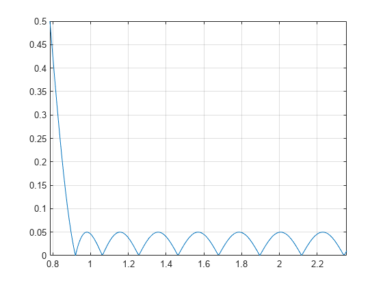
Inspect the stopband ripple in the design withC=1andp=1. The constrained design sets the maximum ripple to be 0.05. Zoom in on the stopband from the cutoff frequency of pi/4 radians/sample to 3pi/4 radians/sample.
figure; plot(w,abs(h1)); set(gca,'xlim',[pi/4 3*pi/4]); gridon;
Extended Capabilities
See Also
diric|fdesign.decimator|firhalfband|firnyquist|firgr|ifir|iirgrpdelay|iirlpnorm|iirlpnormc|fircls|firls|firpm|sinc
Select a Web Site
Choose a web site to get translated content where available and see local events and offers. Based on your location, we recommend that you select:.
Selectweb siteYou can also select a web site from the following list:
Americas
- América Latina(Español)
- Canada(English)
- United States(English)
Europe
- Belgium(English)
- Denmark(English)
- Deutschland(Deutsch)
- España(Español)
- Finland(English)
- France(Français)
- Ireland(English)
- Italia(Italiano)
- Luxembourg(English)
- Netherlands(English)
- Norway(English)
- Österreich(Deutsch)
- Portugal(English)
- Sweden(English)
- Switzerland
- United Kingdom(English)