fanbeam
Fan-beam transform
Description
F= fanbeam(I,D,Name,Value)
[also returns the location of fan-beam sensors inF,fanSensorPos,fanRotAngles] = fanbeam(___)fanSensorPosand the rotation angles where the fan-beam projections are calculated infanRotAngles.
Examples
Compute Fan-beam Projections for Rotation Angles Over Entire Image
Set the IPT preference to make the axes visible.
iptsetpref('ImshowAxesVisible','on')
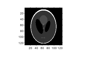
Create a sample image and display it.
ph = phantom(128); imshow(ph)
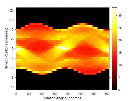
Calculate the fanbeam projections and display them.
[F,Fpos,Fangles] = fanbeam(ph,250); figure imshow(F,[],“XData”,Fangles,'YData',Fpos,...'InitialMagnification','fit') axisnormalxlabel('Rotation Angles (degrees)') ylabel('Sensor Positions (degrees)') colormap(gca,hot), colorbar
Compute Radon and Fan-beam Projections and Compare Results
Compute fan-beam projections for 'arc' geometry.
I = ones(100); D = 200; dtheta = 45; [Farc,FposArcDeg,Fangles] = fanbeam(I,D,...'FanSensorGeometry','arc',...'FanRotationIncrement',dtheta);
Convert angular positions to linear distance along x-prime axis.
FposArc = D*tan(FposArcDeg*pi/180);
Compute fan-beam projections for 'line' geometry.
[Fline,FposLine] = fanbeam(I,D,...'FanSensorGeometry','line',...'FanRotationIncrement',dtheta);
Compute the corresponding Radon transform.
[R,Rpos]=radon(I,Fangles);
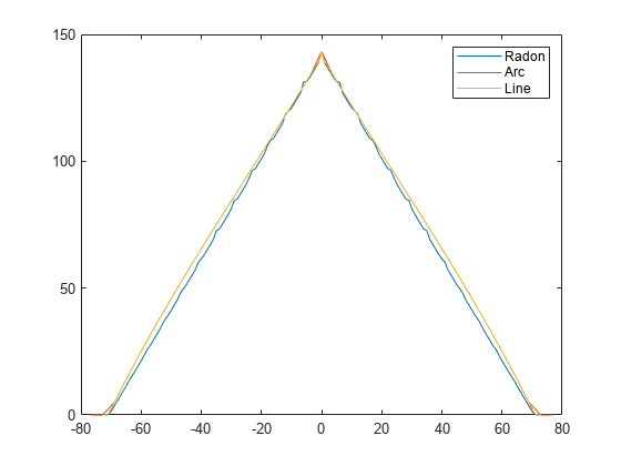
Display the three projections at one particular rotation angle. Note the three are very similar. Differences are due to the geometry of the sampling, and the numerical approximations used in the calculations.
figure idx = find(Fangles==45); plot(Rpos,R(:,idx),...FposArc,Farc(:,idx),...FposLine,Fline(:,idx)) legend('Radon','Arc','Line')
Input Arguments
I—Input image
2-D numeric matrix|2-D logical matrix
Input image, specified as a 2-D numeric matrix or 2-D logical matrix.
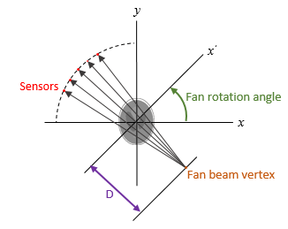
D—距离风扇beam vertex to center of rotation
positive number
Distance in pixels from the fan beam vertex to the center of rotation, specified as a positive number. The center of rotation is the center pixel of the image, defined asfloor((size(I)+1)/2).Dmust be large enough to ensure that the fan-beam vertex is outside of the image at all rotation angles. SeeTipsfor guidelines on specifyingD.
Name-Value Arguments
Specify optional pairs of arguments asName1=Value1,...,NameN=ValueN, whereNameis the argument name andValueis the corresponding value. Name-value arguments must appear after other arguments, but the order of the pairs does not matter.
Example:fanbeam(I,D,FanRotationIncrement=5)
Before R2021a, use commas to separate each name and value, and encloseNamein quotes.
Example:fanbeam(I,D,"FanRotationIncrement",5)
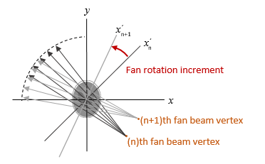
Fan-beam rotation angle increment in degrees, specified as a positive scalar.
Data Types:double
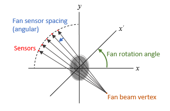
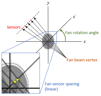
Fan-beam sensor positioning, specified as"arc"or"line".
Value |
Meaning |
Diagram |
|---|---|---|
|
Sensors are spaced at equal angles along a circular arc. The center of the arc is the fan-beam vertex.
|
|
|
Sensors are spaced at equal distances along a line that is parallel to thex'axis. The closest sensor is distance
|
|
Output Arguments
Tips
As a guideline, try makingDa few pixels larger than half the image diagonal dimension, calculated as follows.
sqrt(size(I,1)^2 + size(I,2)^2)
The values returned inFare a numerical approximation of the fan-beam projections. The algorithm depends on the Radon transform, interpolated to the fan-beam geometry. The results vary depending on the parameters used. You can expect more accurate results when the image is larger,Dis larger, and for points closer to the middle of the image, away from the edges.
References
[1]. pp. 92-93.
Version History
Introduced before R2006a
You can also select a web site from the following list:
Americas
- América Latina(Español)
- Canada(English)
- United States(English)
Europe
- Belgium(English)
- Denmark(English)
- Deutschland(Deutsch)
- España(Español)
- Finland(English)
- France(Français)
- Ireland(English)
- Italia(Italiano)
- Luxembourg(English)
- Netherlands(English)
- Norway(English)
- Österreich(Deutsch)
- Portugal(English)
- Sweden(English)
- Switzerland
- United Kingdom(English)