文档Help Center文档
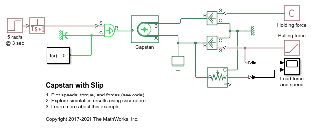
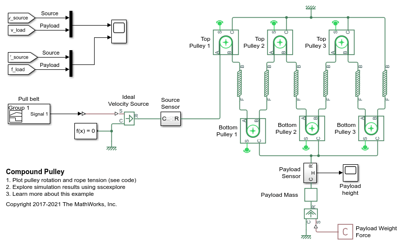
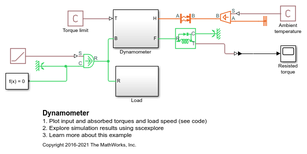
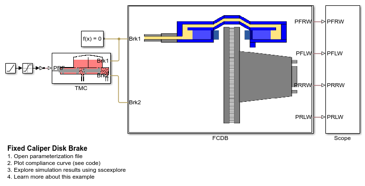
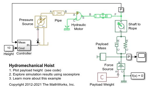
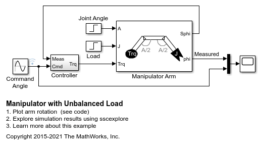
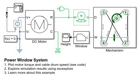
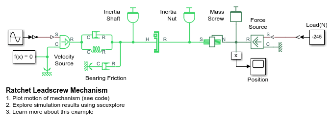
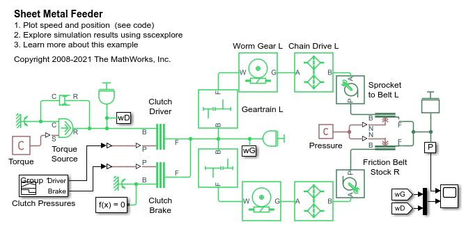
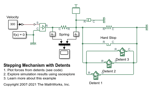
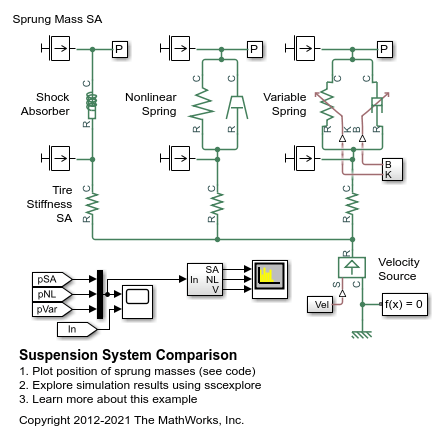
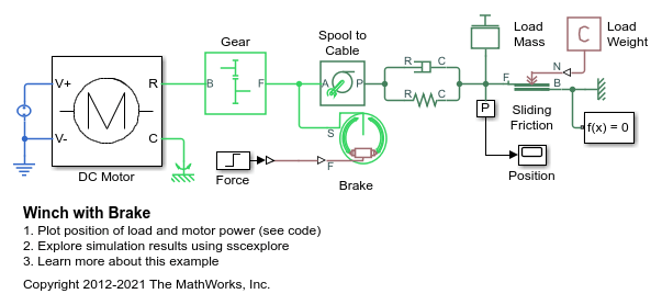
These examples demonstrate the diverse capabilities ofSimscape™ Driveline™using common industrial applications.
一个绞盘represented by a Belt Pulley block from the Simscape™ Driveline™ library. A 100-N tension applied to belt end A holds a variable load at end B in place, even as the load increases. When the load force increases past the friction limit, the belt slips. Increasing the friction by using a higher friction coefficient or wrap angle allows the pulley to hold an even greater load force. This example also shows how suddenly turning the capstan, starting at 5 seconds, causes momentary slip, which is quickly recovered.
A block and tackle system that is represented by the Belt Pulley and Rope blocks from the Simscape™ Driveline™ library. This compound pulley is rigged as a threefold purchase with two triple blocks. The system has a mechanical advantage of 6.
Two methods to create a constant rotational velocity output using universal joints. In the first method, the angle of the universal joints is exactly opposite. The output shaft axis is parallel to the input shaft axis, but offset by some distance.
This examples shows a dynamometer resisting a load from a prime mover. This prime mover is modeled as a torque source and could be an internal combustion engine, electric drive, or a hydraulic motor. The dyno absorbs input torque up to its limit, and allows rotation of connected loads for torques beyond. The dyno itself is modeled using the Fundamental Friction Clutch with static and dynamic limits set to the torque limit.
Model, parameterize, and test a caliper disk brake. The example uses numerical data extracted from the tandem master cylinder datasheet to identify an optimal design for the caliper disk brake. The example shows how to generate a compliance curve for the caliper disk brake.
A hydromechanical hoist lifting a payload. An ideal hydraulic motor is driven by the pressure commanded by a controller. The controller estimates the current height of the payload by reading the angular velocity from the motor's flexible shaft. The rope is represented as a spring and damper, and the payload is modeled as a mass with gravitational force.
A manipulator controlling the orientation of an end effector through an unbalanced arm. The motor is represented as a torque source using simple proportional control. The load on the end effector increases sharply when the end effector secures the load. Noise is introduced at each sensor to measure its effect on controller performance.
A motor-driven power window system. A DC motor drives the power window mechanism via a self-locking worm gear with the ratio 1 : 50. The power window mechanism consists of a cable drum and four pulleys all connected by a cable. The window is attached to the cable at two points by the lift plate. This ensures both sides of the window move at the same speed and in the same direction, keeping the window level. The model also includes viscous friction in the guide rails.
A stepping mechanism constructed from a self-locking leadscrew and a unidirectional clutch. The input shaft of the unidirectional clutch oscillates with velocity amplitude 2 rad/s and frequency 0.5 rad/s. The unidirectional clutch drives the load via the leadscrew. The lead angle of the screw is small enough to ensure self-locking operation due to geometry and thread friction. As a result, the load maintains its position while the clutch input shaft rotates in the opposite direction and the load moves in incremental steps of about 25 mm.
A feeding mechanism of a sheet metal cutter. Two slitted rolls are driven by a torque motor through two mechanical drivetrains. Each drivetrain consists of a spur gear train, worm gear, and a chain drive. The sprocket of the chain drive is connected to its respective slitted roll. The interaction between the rolls and the sheet metal is simulated by the Loaded Contact Translational Friction blocks.
A mass moving along a slider and held at set points with translational detents. The mass is suspended between two springs and is subject to viscous friction. Three detents hold the load at 50, 75, and 125 mm. The peak force of these detents is 20, 30, and 20 N respectively. To move the load past each detent, the spring pushing the load must deform enough to produce a force that overcomes the holding force of the detents.
A testbed containing three sets of springs and dampers excited by the same oscillating velocity source. The first uses the Shock Absorber block and includes linear stiffness and damping. Optional friction and hard stops are not used. The second shock absorber uses a Nonlinear Translational Spring and a Nonlinear Translational Damper specified by symmetric polynomials. The third uses a Variable Translational Spring and Variable Translational Damper. The spring constant is varied during the simulation using open loop control and the damping coefficient adjusts to ensure critical damping is achieved. Closed loop control can be added to simulate an adaptive suspension system.
A winch driven by a DC motor and controlled with a double-shoe brake. The motor is connected to a 24 volt supply, and the shaft speed is stepped down with a 10:1 gear reduction. The pulled load is modeled as a mass with sliding friction. At a simulation time of six seconds, force is applied to an internal double-shoe brake, stopping the winch.
You clicked a link that corresponds to this MATLAB command:
Run the command by entering it in the MATLAB Command Window. Web browsers do not support MATLAB commands.
Choose a web site to get translated content where available and see local events and offers. Based on your location, we recommend that you select:.
You can also select a web site from the following list:
Select the China site (in Chinese or English) for best site performance. Other MathWorks country sites are not optimized for visits from your location.
Contact your local office
Get trial now