Create and Use an Oval Track
You can create a oval track withRoadRunnerand use it in a Vehicle Dynamics Blockset™ simulation that co-simulates with Unreal®. This example provides the workflow for creating the oval track that is used in theFollow Waypoints Around Oval Trackexample.
Before you start, make sure that you have the products required to follow the workflow.
| Step | Required Products | |
|---|---|---|
1 |
RoadRunner |
|
2 |
RoadRunner Unreal Engine®4.26 RoadRunnerplugin Visual Studio®2019 |
|
| 3 | ||
4 |
Unreal Engine 4.26 Vehicle Dynamics Blockset Vehicle Dynamics Blockset Interface for Unreal Engine 4 Projects |
|
Step 1: Create Track inRoadRunner
In this example, you create the oval track specified in the following figure. The locations and reference poses are in theRoadRunnercoordinate system, (X,Y,θ). The locations,XandY, are in m. The reference poses,θ, are in deg.
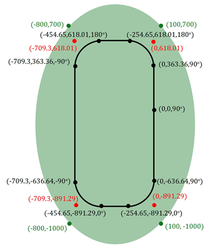
| Legend | |
|---|---|
Green |
Locations of patch boundaries,X,Y |
Red |
Intersection points of straight-line segments,X,Y |
Black |
Track locations and reference poses,X,Y,θ |
UseRoadRunnerto create the oval track. For more information about creating tracks, see
Create Straight Line Segments
Open theRoad Plan Tool.
Navigate toLibrary Browser>RoadStyles. Select
Residential.Right-click to place the start and endpoints of a straight-line road.
After each straight segment, left-click and repeat the preceding step.
Selecting the road control points. Use the preceding figure to the enter coordinate information.
Create Circular Arc
Open theRoad Plan Tool. If you are continuing from creating the straight-line segments, the
Residentialroad is the default road.Right-click to place the start and endpoints of the arc. If you use this method to connect straight lines, there might be multiple control points. Delete all but one control point.
To create a control point, right-click anywhere in the road. To position it as specified in red in the preceding figure, left-click in each arc control point.
要创建圆弧,编辑的位置the control points. If the start of a road marks the end of another,RoadRunnerconnects them.
Adjust Road Width
Open theLane Width Tool.
Select the road that needs the width adjustment.
To adjust the road width, select any purple or red segment.
Modify the lines so that the entire width of the road is 14 m, or 7 m from the road centerline to each edge.
Create Patch
Open theSurface Tool.
Right-click to create four nodes.
Right-click the first node to close the loop. By default, the surface is green.
Add Trees
To provide visual cues that indicate how fast the vehicle is traveling, you can add trees.
Open theProp Curve Tool.
Select an asset to place in the scene. For example, select
Props\Trees\Eucalyptus_Sm01.Right-click to select the inner boundary of the trajectory. To limit the trees in the green areas, adjust the tangents at the control points.
To facilitate faster import into Unreal Engine, choose an appropriate spacing that limits the number of trees in the scene. The import time is proportional to the number of scene assets.
Step 2: Export Track FromRoadRunner
InRoadRunner, open the scene.
SelectFile>Export>Unreal (.fbx + .xml)
In the Export Unreal dialog box, selectSplit by Segmentationand export folder. ClickExport.
Step 3: Import Track toUnreal Engine
After exporting fromRoadRunner, you import the data into Unreal Engine.
Create Empty Project
Create an empty project by following the steps listed inCreate Empty Project in Unreal Engine.
Acquire and RebuildRoadRunnerPlugins
Download theRoadRunnerplugin. For more information, seeDownloading Plugins(RoadRunner).
Extract theRoadRunnerplugin
.zipfile. Locate theRoadRunnerImporterandRoadRunnerMaterialsfolders under the Unreal Engine plugins.Note
The Unreal Engine plugin folder also contains a
RoadRunnerCarlaintegration plugin. If you are not using CARLA, do not copy this folder.Copy the
RoadRunnerImporterandRoadRunnerMaterialsfolders into thePluginsfolder under the project folder. If a Plugins folder does not exist, create one.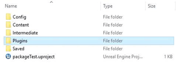
Use a or b to rebuild the plugin.
Generate the project files.
Windows®– Right-click the .
uprojectfile and selectGenerate Visual Studio project files.Linux®– Set environment variable
UE4_ROOTto your Unreal Engine installation folder. At the command line, run this code:$UE4_ROOT/GenerateProjectFiles.sh -project="
" -game -engine
Open the project. SelectYesto build the plugins.
If both a and b fail, try using Visual Studio to build the binaries.
Verify that theRoadRunnerand MathWorks Interface plugins are enabled. SelectEdit>Plugins. Confirm thatEnabled被选中。

Import toUnreal Engine
In the Unreal Editor, clickImport. Select the
.fbxfile from Step 2.Note
SelectingFile>Import Into Leveldoes not use the exportedRoadRunner
xml. Instead, it uses the Unreal importer.Use the default options in theRoadRunnerImport Options Dialog Box. ClickImport.
Under theScenetab, selectImport as Dynamic. This enables translation of the whole scene.
UnderStatic Meshes, clearRemove Degenerates. SetNormal Input Methodas
Input Normals. ClickImport. The import can take up to 1 hour to complete.In theWorld Outliner, select the scene that you imported, for example
FbxScene_OvalTrack1. To align theRoadRunnerand Unreal coordinate systems, enter a 90° rotation about theZ-axis.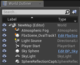
Optionally, consider using the editor to add terrain and foliage in the scene.
Save the project (
.uproject) file. Close the Unreal Editor.

Step 4: Co-Simulate inVehicle Dynamics Blockset
Open the Simulink®model. Do not open the Unreal Editor.
At the command-line, run these commands:
sim3d.Engine.stop sim3d.Engine.start
Open theSimulation 3D Scene Configurationblock.
SetScene sourceto
Unreal Editor.SetProjectto the project (
.uproject) file that you saved inStep 3: Import Track to Unreal Engine.ClickApply.
ClickOpen Unreal Editor.
The project opens in the Unreal Editor.
SelectBlueprints>Open Level Blueprint.
In the level blueprint:
SelectFile>Reparent Blueprint.
SelectSim3dLevelScriptActor.
ClickSave.
Close the level blueprint.
In the editor, clickSave Current.
This ensures that the vehicle identifies the ground properly during co-simulation.
Run the simulation.
In the Simulink model, clickRun.
Because the source of the scenes is the project opened in the Unreal Editor, the simulation does not start.
Verify that the Diagnostic Viewer window in Simulink displays this message:
In the Simulation 3D Scene Configuration block, you set the scene source to 'Unreal Editor'. In Unreal Editor, select 'Play' to view the scene.This message confirms that Simulink has instantiated the vehicles and other assets in the Unreal Engine 3D environment.
In the Unreal Editor, clickPlay. The simulation runs in the scene currently open in the Unreal Editor.
See Also
Simulation 3D Scene Configuration
Related Examples
More About
- Integrate Scenes with MATLAB and Simulink(RoadRunner)
You can also select a web site from the following list:
Americas
- América Latina(Español)
- Canada(English)
- United States(English)
Europe
- Belgium(English)
- Denmark(English)
- Deutschland(Deutsch)
- España(Español)
- Finland(English)
- France(Français)
- Ireland(English)
- Italia(Italiano)
- Luxembourg(English)
- Netherlands(English)
- Norway(English)
- Österreich(Deutsch)
- Portugal(English)
- Sweden(English)
- Switzerland
- United Kingdom(English)