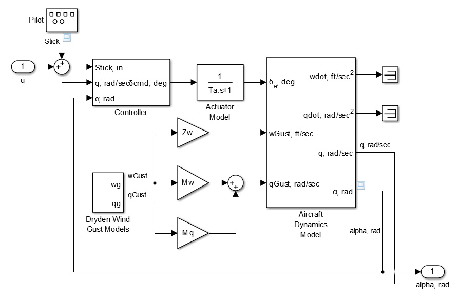
A block diagram consists ofblocksthat represent different parts of a system andsignal linesthat define the relationship between the blocks. Block diagrams are widely used by engineers for controls, signal processing, communications, and mechatronics.
Engineers build and use block diagrams to:
- Provide a high-level graphical representation of real-world systems, as in the figure below
- Understand the relationship and interdependencies among different parts of a system, such as ahouse heating system
- Analyze dynamic system behavior in time andfrequency domains
Engineers rely on the Simulink®environment to build and simulate block diagrams for multidomain systems efficiently. This environment provides:
- A graphical editorfor building and managing hierarchical block diagrams
- An extensive set ofblock librariesand templates to design block diagrams
- Solversto simulate a range of systems, including continuous-time (analog), discrete-time (digital), hybrid (mixed-signal), discrete-event, and multirate systems
- For details on modeling and simulating block diagrams, see万博1manbetx.

