Field-Oriented Control of PMSM Using SI Units
This example implements the Field-Oriented Control (FOC) technique to control the speed of a three-phase Permanent Magnet Synchronous Motor (PMSM). However, instead of the per-unit representation of quantities(for details about the per-unit system, seePer-Unit System), the FOC algorithm in this example uses the SI units of signals to perform the computations. These are the signals and their SI units:
Rotor speed - Radians/ sec
Rotor position - Radians
Currents - Amperes
Voltages - Volts
Field-oriented control (FOC) needs a real time feedback of the rotor position. This example uses the quadrature encoder sensor to measure the rotor position. For details about FOC, seeField-Oriented Control (FOC).
Models
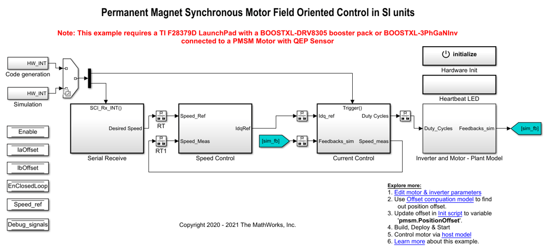
The example includes the modelmcb_pmsm_foc_qep_f28379d_SIUnit.
You can use this model for both simulation and code generation. You can also use the open_system command to open the Simulink® model. For example, use this command for a F28379D based controller:
open_system('mcb_pmsm_foc_qep_f28379d_SIUnit.slx');
Required MathWorks® Products
To simulate model:
Motor Control Blockset™
To generate code and deploy model:
Motor Control Blockset™
Embedded Coder®
Embedded Coder® Support Package for Texas Instruments™ C2000™ Processors
Fixed-Point Designer™ (only needed for optimized code generation)
Prerequisites
1.Obtain the motor parameters. We provide default motor parameters with the Simulink® model that you can replace with the values from either the motor datasheet or other sources.
However, if you have the motor control hardware, you can estimate the parameters for the motor that you want to use, by using the Motor Control Blockset parameter estimation tool. For instructions, seeEstimate PMSM Parameters Using Recommended Hardware.
The parameter estimation tool updates themotorParamvariable (in the MATLAB® workspace) with the estimated motor parameters.
2.If you obtain the motor parameters from the datasheet or other sources, update the motor parameters and inverter parameters in the model initialization script associated with the Simulink® models. For instructions, seeEstimate Control Gains and Use Utility Functions.
If you use the parameter estimation tool, you can update the inverter parameters, but do not update the motor parameters in the model initialization script. The script automatically extracts motor parameters from the updatedmotorParamworkspace variable.
Simulate Model
This example supports simulation. Follow these steps to simulate the model.
1.Open the model included with this example.
2.ClickRunon theSimulationtab to simulate the model.
3.ClickData Inspectoron theSimulationtab to view and analyze the simulation results.
Generate Code and Deploy Model to Target Hardware
This section instructs you to generate code and run the FOC algorithm on the target hardware.
The example uses a host and a target model. The host model is a user interface to the controller hardware board. You can run the host model on the host computer. The prerequisite to use the host model is to deploy the target model to the controller hardware board. The host model uses serial communication to command the target model and run the motor in a closed-loop control.
Required Hardware
这个例子支持这个硬件配置万博1manbetx。You can also use the target model name to open the model for the corresponding hardware configuration, from the MATLAB® command prompt.
LAUNCHXL-F28379D controller + BOOSTXL-DRV8305 inverter:mcb_pmsm_foc_qep_f28379d_SIUnit
For connections related to the preceding hardware configuration, seeLAUNCHXL-F28069M and LAUNCHXL-F28379D Configurations.
Generate Code and Run Model on Target Hardware
1.Simulate the target model and observe the simulation results.
2.Complete the hardware connections.
3.The model automatically computes the ADC (or current) offset values. To disable this functionality (enabled by default), update the value 0 to the variable inverter.ADCOffsetCalibEnable in the model initialization script.
Alternatively, you can compute the ADC offset values and update it manually in the model initialization scripts. For instructions, seeRun 3-Phase AC Motors in Open-Loop Control and Calibrate ADC Offset.
4.Compute the quadrature encoder index offset value and update it in the model initialization scripts associated with the target model. For instructions, seeQuadrature Encoder Offset Calibration for PMSM Motor.
5.Open the target model. If you want to change the default hardware configuration settings for the model, seeModel Configuration Parameters.
6.Load a sample program to CPU2 of LAUNCHXL-F28379D, for example, program that operates the CPU2 blue LED by using GPIO31 (c28379D_cpu2_blink.slx), to ensure that CPU2 is not mistakenly configured to use the board peripherals intended for CPU1.
7.ClickBuild, Deploy & Starton theHardwaretab to deploy the target model to the hardware.
8.Click thehost modelhyperlink in the target model to open the associated host model. You can also use the open_system command to open the host model. For example, use this command for a F28069M based controller:
open_system('mcb_pmsm_SIUnit_host_model.slx');

For details about the serial communication between the host and target models, seeHost-Target Communication.
9.In the host model, open the blocks Host Serial Setup, Host Serial Receive, and Host Serial Transmit, and select aPort.
10.更新参考速度值主机模型.
11.ClickRunon theSimulationtab to run the host model.
12.Change the position of the Start / Stop Motor switch to On, to start running the motor.
13.Observe the debug signals from the RX subsystem, in the Time Scope of host model.
You can also select a web site from the following list:
Americas
- América Latina(Español)
- Canada(English)
- United States(English)
Europe
- Belgium(English)
- Denmark(English)
- Deutschland(Deutsch)
- España(Español)
- Finland(English)
- France(Français)
- Ireland(English)
- Italia(Italiano)
- Luxembourg(English)
- Netherlands(English)
- Norway(English)
- Österreich(Deutsch)
- Portugal(English)
- Sweden(English)
- Switzerland
- United Kingdom(English)